APAC - English
Suspended scaffolds are the primary method used to access building exteriors at height. From routine window cleaning to complex facade inspections and repairs, these systems enable safe and efficient work across vertical surfaces that would otherwise be inaccessible. In modern construction and building maintenance, suspended access is not optional. It is a core part of how buildings are designed to be maintained throughout their lifecycle.
However, not all hanging scaffold systems are equal. The type of suspended scaffold specified has a direct impact on safety, operational efficiency, access coverage, and long-term cost. For architects, facade consultants, and building operators, selecting the right system is not simply a matter of equipment choice. It is a design decision that affects how the building performs over decades.
The most common type of suspended scaffold used in facade access is examined from a specification and performance perspective, including why it is the preferred solution across most building types and how to select the right hanging scaffold system based on height, facade geometry, and access frequency. The main suspended scaffold types are also covered, together with the governing standards such as OSHA, CSA, EN 1808, and ASME A120.1.
Self-powered suspended platforms used in facade access range from single-operator systems designed for light tasks to fully engineered hanging scaffold systems integrated into permanent building maintenance infrastructure. Each type serves a specific purpose depending on building height, facade complexity, and maintenance requirements.
Understanding the differences between these systems is essential before identifying the most common and most appropriate solution.
A two-point self-powered suspended platform is suspended by two wire ropes or cables, one positioned at each end of the platform. The platform is raised and lowered using motorized hoists, allowing controlled vertical movement along the building facade.
This is the most common type of suspended scaffold used in facade access. It is widely adopted because it provides the optimal balance between flexibility, load capacity, and integration with permanent building systems. In professional applications, the two-point platform operates as part of a larger facade access system. It is supported by parapet clamps or roofbeams.
Modern powered platforms use traction hoists (e.g., Tractel Tirak, Power Climber LSC, Sky Climber) engineered for reliability at height, with built-in safety features including emergency descent, slack-cable detection, tilt sensors, overload protection, and limit switches. Typical applications include facade cleaning, inspection, painting, glass replacement, and maintenance across low-rise, mid-rise, and high-rise buildings. Standard two-point traction-hoist platforms reliably service buildings up to ~200 m. Beyond this, multi-stage configurations and BMU-supported systems are typically specified.
A single-point adjustable suspension scaffold is a manned platform suspended by one rope from an overhead support, typically operated by one worker (29 CFR 1926.452(o)). A boatswain’s (bosun’s) chair is a related but distinct seat-board variant used for short-duration access, governed by the same subsection.
In facade access, single-point suspension systems are commonly used in areas where a two-point suspended platform is too large to safely access confined facade sections, narrow recesses, or restricted architectural conditions. These systems can form part of a permanent facade access strategy, particularly on buildings with complex geometries where localized access is required. While single-point systems support only one operator and have lower tool and material capacity than two-point platforms, they provide an effective solution for targeted maintenance, inspection, and repair work in difficult-to-access areas. In many projects, they operate alongside larger permanent facade access systems to provide complete building coverage.
A multi-point adjustable scaffold is a hanging scaffold platform supported by more than two suspension points. These systems are designed to carry longer platforms or higher loads, making them suitable for large-scale facade projects or buildings with complex geometries.
In facade access applications, multi-point systems are typically custom-engineered. Modular self-powered platforms are a common example. These platforms can be assembled on-site to match the required length and configuration, allowing access across wide facade areas. This type of system is often specified when a standard two-point platform cannot provide sufficient coverage. For example, buildings with large continuous elevations or irregular geometries may require multi-point support to maintain stability and performance.
Due to their increased complexity and load requirements, multi-point hanging scaffold systems require detailed engineering design and secure anchorage. They are not general-purpose systems and are typically used in specialized scenarios.
The two-point self-powered modular platform is the most commonly used suspended access system in facade maintenance. Commonly referred to as a swing stage or self-powered platform, it is considered the industry standard because it delivers reliable access, flexibility, and operational efficiency across a wide range of building conditions.
Its dominance is not accidental. It is the result of its ability to meet the technical, operational, and regulatory requirements of modern buildings more effectively than any other system.
One of the key reasons the two-point adjustable scaffold is so widely used is its versatility. It can be configured to suit buildings of varying heights, sizes, and facade conditions. Platform lengths can be adjusted to match the width of the working area, and systems can support one to three operators depending on load rating. This flexibility allows the same core system to be used across a wide range of applications.
This adaptability is critical for accessing complex facade geometries. Buildings with recessed panels, balconies, overhangs, or irregular surfaces require systems that can adjust position dynamically. The two-point platform provides this capability without requiring entirely custom solutions. From a height perspective, these systems can be engineered to operate on buildings up to approximately 200 metres. Hoisting systems, wire rope specifications, and structural supports are all designed to perform reliably at these heights.
Another key advantage of the two-point self-powered suspended platform is its ability to integrate seamlessly with permanent facade access infrastructure. On most modern buildings, the hanging scaffold platform is not used as a standalone system. Instead, it forms part of a larger, engineered solution that includes roof-mounted equipment and anchor systems.
Davit systems provide fixed or portable suspension points for the platform. Powered davit carriages allow movement along roof tracks. Building Maintenance Units (BMUs) offer full facade coverage by travelling across the roof and lowering the platform to different elevations. Monorail systems can be used where roof-mounted equipment is not feasible, allowing horizontal movement along the building facade. Tieback anchors and Intermittent Stabilisation Anchors ensure the platform remains stable during operation, particularly on taller buildings where wind and movement become critical factors. This level of integration transforms the hanging scaffold platform from a temporary access tool into a permanent building system. It ensures consistent performance, reduces setup time, and improves overall safety.
Safety compliance is a fundamental requirement for any suspended scaffold system used in facade access. The two-point adjustable scaffold is designed to meet the most widely recognized standards across global markets.
In the United States, OSHA defines fall protection and safety requirements for suspended scaffolds. In Europe, EN 1808 governs suspended access equipment, including design, safety factors, and operational requirements. In North America, ASME A120.1 and CAN/CSA-Z271 provide standards for powered platforms used in building maintenance. One of the most critical requirements under EN 1808 is the rope safety factor. Under EN 1808:2015 §6.1.2.5, each suspension rope’s minimum breaking load must be at least 12 times the maximum static rope tension — this is a per-rope requirement, not a multiplier on the platform’s working load.
Tieback anchors and stabilization systems are also subject to strict requirements. On buildings above 130 ft (39.6 m) in height, stabilization anchors must be installed at defined intervals to control platform movement and maintain safe working conditions. The ability of the two-point adjustable scaffold to meet these standards consistently is a major factor in its widespread adoption.
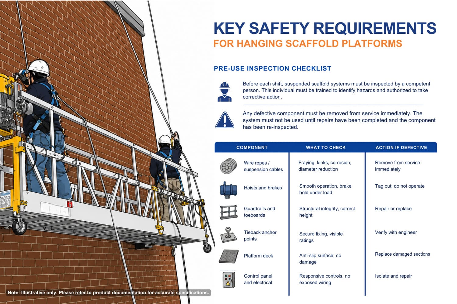
Working on a hanging scaffold platform involves inherent risks. Safety is achieved through a combination of engineered system design and strict operational procedures.
Personal fall arrest systems (PFAS) are mandatory for all suspended scaffold operations. Workers must be connected to an independent lifeline that is completely separate from the scaffold’s suspension system. This separation is critical. If the scaffold system were to fail, the fall arrest system must remain intact and capable of supporting the worker independently.
Guardrail systems provide an additional layer of protection. Guardrails on suspended platforms must withstand 200 lb (toprail) and 150 lb (midrail) under OSHA 29 CFR 1910.29 / 1926.451. EN 1808 §6.4 specifies a minimum guardrail height of 1.0 m and equivalent load-resistance requirements via design calculation. Properly designed anchor systems, including tieback anchors and horizontal lifelines, are essential to supporting these safety measures.
Before each shift, suspended scaffold systems must be inspected by a competent person. This individual must be trained to identify hazards and authorized to take corrective action. Any defective component must be removed from service immediately. The system must not be used until repairs have been completed and the component has been re-inspected.
| Component | What to Check | Action if Defective |
|---|---|---|
| Wire ropes / suspension cables | Fraying, kinks, corrosion, diameter reduction | Remove from service immediately |
| Hoists and brakes | Smooth operation, brake hold under load | Tag out; do not operate |
| Guardrails and toeboards | Structural integrity, correct height | Repair or replace |
| Tieback anchor points | Secure fixing, visible ratings | Verify with engineer |
| Platform deck | Anti-slip surface, no damage | Replace damaged sections |
| Control panel and electrical | Responsive controls, no exposed wiring | Isolate and repair |
Selecting the right hanging scaffold system requires a clear understanding of the building’s characteristics and maintenance requirements. The decision should be made during the design phase wherever possible.
For buildings with standard facades up to approximately 150 metres, a two-point adjustable scaffold combined with a davit system or compact BMU provides a reliable and efficient solution. For buildings with complex geometries, such as curved facades, setbacks, or recessed sections, more advanced systems are required. Modular BMUs with telescopic and slewing jibs allow the platform to reach areas that would otherwise be inaccessible. For very tall buildings, typically above 150 metres, additional structural considerations come into play. The weight and length of suspension ropes become significant factors, requiring custom-engineered solutions tailored to the specific project.
Buildings that require regular facade maintenance should be equipped with permanent facade access systems. These systems provide consistent, safe access without the need for repeated setup and dismantling. For existing buildings that were not designed with permanent systems, retrofit solutions are available. However, these require careful structural assessment and engineering design to ensure compliance and performance.
For low-rise buildings with infrequent access requirements, portable davit systems combined with a hanging scaffold platform may be sufficient. Even in these cases, permanent anchor infrastructure must be installed to ensure safety.
The suspended scaffold system specified for a building defines how maintenance work will be carried out for decades. Choosing the right system ensures safer operations, better access coverage, and lower long-term costs.
Facade Access Solutions supports projects from initial concept through to long-term operation. This includes system specification, engineering design, installation, commissioning, and ongoing service. If you are planning a new project or assessing an existing building, early consultation is critical.
Disclaimer: Graphics shown are illustrative only and do not represent actual products, equipment, or real-life conditions.
A large portion of today’s commercial and high-rise buildings were designed before permanent facade access systems became a regulated requirement. As a result, many properties still operate without a compliant roof anchor system, creating a fundamental gap in safe facade maintenance capability. This is not a minor oversight. Without properly designed anchors, routine cleaning, inspection, and repair either cannot be carried out safely or rely on temporary access solutions that introduce higher risk, inconsistent compliance, and increased long-term cost.
Global standards governing roof-anchor retrofits for facade maintenance differ by use case. For personal fall protection anchors: EN 795 (Europe), OSHA 29 CFR 1910.140 (US general industry), CAN/CSA-Z259.15 (Canada), AS/NZS 1891.4 (Australia/NZ). For suspended-equipment tieback anchors used in BMU/davit systems: OSHA 29 CFR 1910.66 Appendix C (US), EN 1808 (Europe), CAN/CSA-Z271 (Canada), AS/NZS 1418.13 (Australia/NZ). For construction-phase fall protection: OSHA 29 CFR 1926.502 (US).
Retrofitting roof anchors requires a clear understanding of key design considerations, the anchor types suited to existing buildings, and the role of a facade access specialist in delivering a compliant, fully functional system.
Many mid-rise and high-rise buildings constructed before the 1990s were not designed with permanent facade access systems in mind. Anchor systems were rarely included in the original specification, as facade maintenance was typically addressed through temporary or manual methods. As buildings age, however, the need for regular inspection, cleaning, and repair increases, exposing the limitations of these outdated approaches.
At the same time, international standards have become more defined and widely enforced. EN 795 in Europe, OSHA 29 CFR 1926.502 in the United States, CAN/CSA-Z91 in Canada, and AS/NZS 4488 in Australia and New Zealand now establish clear requirements for load ratings, safety factors, and installation criteria. Many markets across Southeast Asia and the Middle East are also aligning local regulations with these frameworks, increasing scrutiny on existing buildings.
The absence of a compliant anchor system does not remove the requirement for facade maintenance. Instead, it shifts the burden to temporary access solutions that introduce higher safety risks, increased labour costs, and greater liability exposure for building owners and operators.
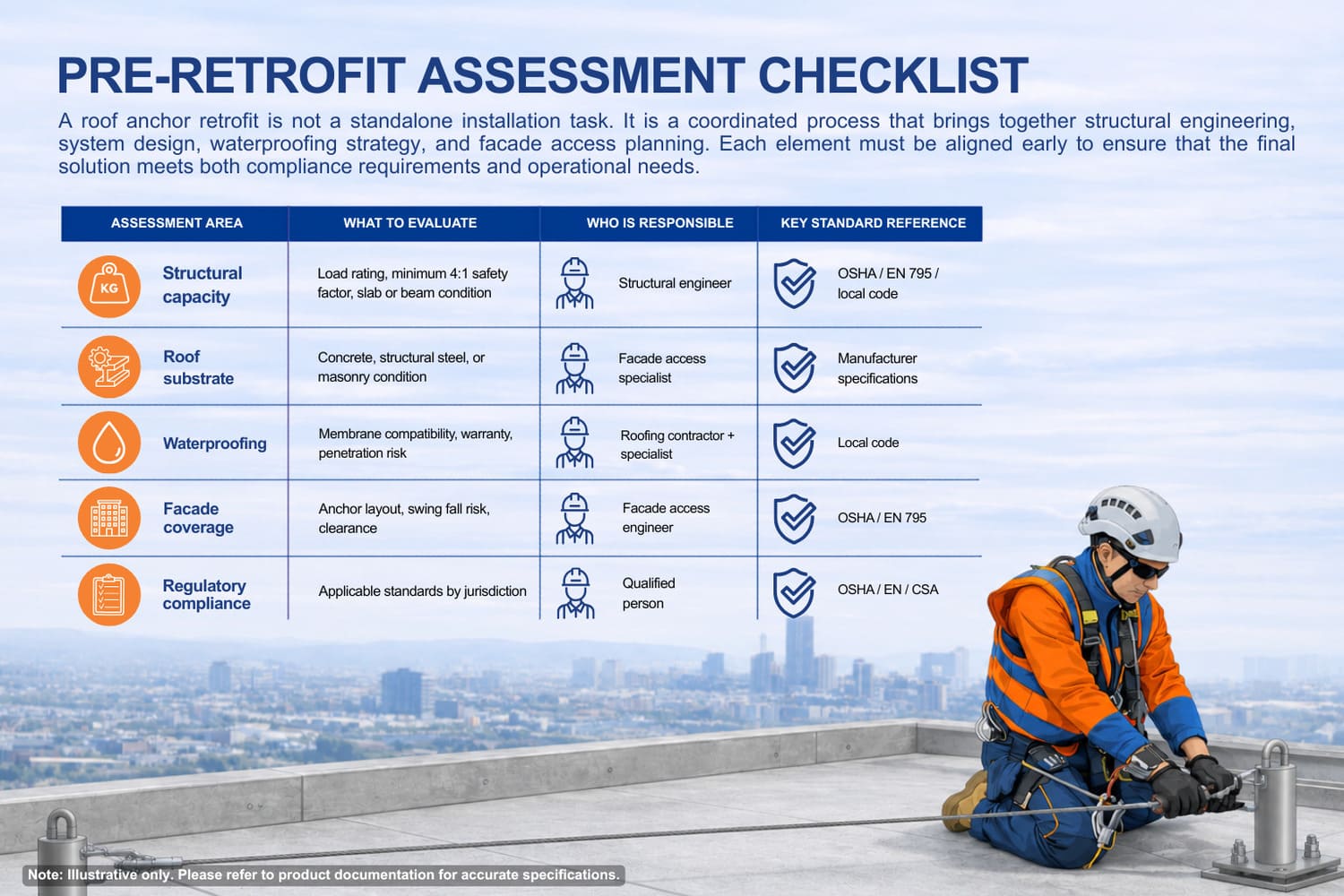
A roof anchor retrofit is not a standalone installation task. It is a coordinated process that brings together structural engineering, system design, waterproofing strategy, and facade access planning. Each element must be aligned early to ensure that the final solution meets both compliance requirements and operational needs.
| Assessment Area | What to Evaluate | Who is Responsible | Key Standard Reference |
|---|---|---|---|
| Structural capacity | Load rating, minimum 4:1 safety factor, slab or beam condition | Structural engineer | OSHA / EN 795 / local code |
| Roof substrate | Concrete, structural steel, or masonry condition | Facade access specialist | Manufacturer specifications |
| Waterproofing | Membrane compatibility, warranty, penetration risk | Roofing contractor + specialist | Local code |
| Facade coverage | Anchor layout, swing fall risk, clearance | Facade access engineer | OSHA / EN 795 |
| Regulatory compliance | Applicable standards by jurisdiction | Qualified person | OSHA / EN / CSA |
The retrofit process begins with a structural assessment. Before any anchor is specified or installed, a qualified structural engineer must confirm that the building can safely resist the required loads. This is a universal requirement across all jurisdictions.
Anchor load criteria depend on the anchor’s purpose. Suspended-equipment tiebacks under OSHA 1910.66 must hold 5,000 lb in any direction. EN 795 anchor devices are classified Type A–E and proof-tested at 12–22 kN — a pass/fail proof-load regime, not a 4:1 SF approach. AS/NZS 1891.4 specifies a 15 kN single-point static rating. Where adhesive anchors are proposed, pull testing should be incorporated into the assessment phase. Addressing this early ensures that performance is validated before installation begins and prevents delays during project execution.
Following structural verification, the next step is determining the appropriate mounting approach based on the roof substrate. In retrofit projects, the most common substrates are reinforced concrete, structural steel, and masonry. Slab thickness, reinforcement layout, edge distances, and concrete strength all affect anchor design. Adhesive and post-installed anchors must be designed and pull-tested per ACI 318-19 Chapter 17 (US) or EN 1992-4:2018 (Europe). A practical floor of ~150 mm is common, but actual minimum thickness must be verified by the structural engineer for the specific anchor and load case. Matching the anchor system to the substrate is critical to ensuring long-term performance and compliance.
With the mounting strategy defined, attention must shift to the roof’s waterproofing system. Any penetration of the roofing membrane must be properly flashed and sealed to maintain long-term integrity. This requires close coordination between the facade access installer and the roofing contractor.
Where a roof warranty is in place, installation must be reviewed in advance to confirm compliance with manufacturer requirements. In many cases, certified roofing contractors must complete membrane reinstatement to preserve warranty coverage. Where penetration is not acceptable, wall-mounted anchors provide a reliable alternative by attaching to the parapet or structural wall. Flush-mounted anchors also minimize disruption, sitting level with the finished roof and reducing both visual impact and trip hazards.
Once structural and installation constraints are addressed, anchor layout must be engineered to ensure full facade coverage. Anchor positions cannot be determined solely by structural convenience. They must align with the operational requirements of facade maintenance. This includes evaluating the type of access equipment being used, such as outriggers, davits, suspended platforms, or bosun’s chairs. Suspension geometry must be carefully planned, and swing fall risks between anchor points must be mitigated through proper spacing and positioning. For buildings exceeding approximately 40 meters (130 feet), Intermittent Stabilization Anchors (ISAs) must also be incorporated. These anchors stabilize suspended platforms during descent and are required by code in most jurisdictions. Effective facade coverage planning requires a facade access engineer, ensuring that the system delivers complete and safe access across the building envelope.
With the key design considerations established, the next step is selecting the appropriate anchor system. Not every anchor type is suitable for every building. The correct solution depends on substrate conditions, building height, access method, and operational constraints at roof level.
Roof-mounted tieback anchors remain the most widely used solution for facade maintenance. They provide secure connection points for suspended platforms, outriggers, and personal fall protection systems. In retrofit applications, these anchors are installed using embedded bolts, adhesive anchors, or weld-to-steel methods depending on the structure. Standard heights range from 12 to 24 inches above the finished roof level. Tieback anchors are designed to hold 5,000 lb (22.2 kN) in any direction. Standard heights above the finished roof are 12–24 inches.
Where roof penetration is not feasible, wall-mounted tieback anchors provide an effective alternative. These systems are fixed to parapet walls or vertical structural elements, avoiding disruption to the roofing membrane. They are installed using embedded, adhesive, or thru-bolt methods depending on the substrate. Despite the different mounting approach, they maintain the same 5,000 lb load rating as roof-mounted anchors, making them a practical solution for buildings with protected or warranted roof systems.
Flush-mounted anchors are designed for rooftops where accessibility and aesthetics are key considerations. Installed level with the finished roof surface, they reduce trip hazards and maintain a clean architectural profile. They support the same load requirements as standard tieback anchors and can be installed using all common retrofit methods. This makes them particularly suitable for high-traffic roofs or buildings with visible rooftop environments.
Intermittent Stabilization Anchors serve a different function from tieback systems. Rather than securing suspension equipment, they stabilize the platform against the facade during operation, preventing outward movement.
Their use is triggered by building height. On buildings exceeding 130 ft (39.6 m), intermittent stabilization anchors must be installed at intervals not exceeding 50 ft (15 m), with the first anchor positioned within 50 ft of the highest tieback (OSHA 1910.66 Appendix C). Intermittent stabilization anchors must resist 300 lb (1.33 kN) without permanent deformation and 600 lb (2.67 kN) without failure (OSHA 1910.66 App C). ISAs resist platform stabilization forces (inward/outward), not multi-axial fall arrest loads.
| Anchor Type | Best Used For | Mounting Methods | Load Rating | Height |
|---|---|---|---|---|
| Roof-Mounted Tieback | Standard rooftop systems | Embedded, adhesive, weld | 5,000 lbs | 12–24″ |
| Wall-Mounted Tieback | No roof penetration | Thru-bolt, embedded | 5,000 lbs | N/A |
| Flush-Mounted | Aesthetic / high-traffic roofs | All methods | 5,000 lbs | Flush |
| ISA | Tall building stabilization | Drill-in, cast-in | 600 lbs | Per code |
A roof anchor retrofit that is not coordinated by a facade access specialist introduces significant risk. This includes non-compliance with applicable standards, incomplete facade coverage, structural issues, and the potential inability to safely carry out maintenance operations. Facade maintenance anchors are not interchangeable with general fall protection hardware. They must be designed as part of a complete system, integrated with the suspended equipment that will operate from them and aligned with the building’s structural and operational requirements.
Facade Access Solutions supports retrofit projects through its integrated design services, backed by more than 16,000 systems installed globally and a presence across 39 locations. Its experience includes complex high-rise projects such as Burj Khalifa, Merdeka 118, and Shanghai Tower. From structural assessment coordination and anchor layout design to installation, load testing, and ongoing inspection services, the full project lifecycle is covered. This ensures that retrofit systems are not only compliant but also fully functional for long-term facade maintenance.
For project-specific guidance, contact Facade Access Solutions to discuss your retrofit requirements.
Disclaimer: Graphics shown are illustrative only and do not represent actual products, equipment, or real-life conditions.
A building facade inspection is no longer optional. As high-rise buildings continue to age and regulatory pressure increases across global markets, inspections have become a core requirement for safe operation and long-term asset protection. This is not simply a compliance exercise. A structured facade inspection is the most effective way to detect early-stage deterioration before it escalates into a safety risk or a costly repair. Issues such as water ingress, material fatigue, and fixing failures are far easier to manage when identified early.
For building owners, inspections protect asset value and reduce lifecycle costs. For facilities managers, they provide a clear, actionable framework for maintenance planning, risk control, and regulatory compliance.
A building facade inspection is a systematic, professional examination of a building’s exterior envelope. It is conducted to identify structural defects, safety hazards, material deterioration, and compliance gaps. This is not a visual check from the ground. A proper inspection requires close physical access to all areas of the facade, including locations that are difficult to reach or hidden from view. Inspections are typically commissioned by building owners, property managers, and developers for regulatory compliance, insurance requirements, transaction due diligence, and proactive maintenance planning.
A facade inspection evaluates the full building envelope, including cladding systems, concrete surfaces, masonry, glazing, joints, sealants, fixings, and structural connections. Waterproofing elements and drainage systems are also assessed to identify potential water ingress risks.
Facade inspections are carried out by qualified professionals, typically a licensed structural engineer or registered architect with specialist experience in facade systems. In many jurisdictions, regulations define who is permitted to conduct inspections. For example, in New York, inspections must be performed by a Qualified Exterior Wall Inspector (QEWI) under the city’s regulatory framework.
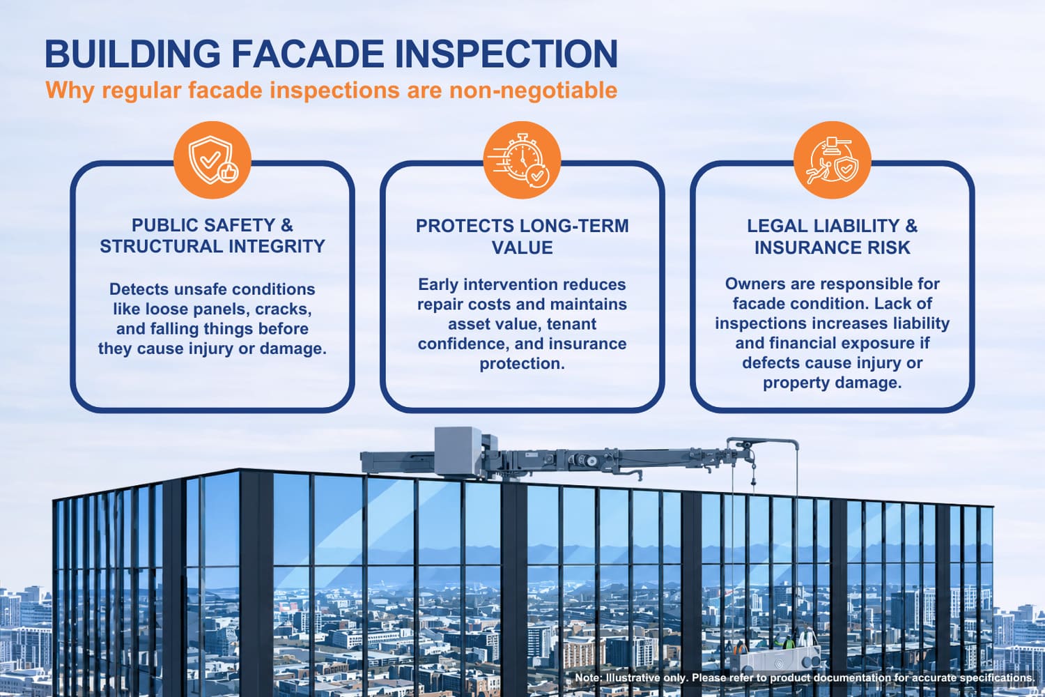
A building’s exterior is its first line of defense against environmental exposure. Thermal movement, moisture, wind loads, and material fatigue all contribute to gradual deterioration. Without regular inspection, minor defects develop into structural failures.
Facade failures pose a direct risk to people on and around the building. Concrete spalling, loose cladding panels, and failed window fixings can result in falling debris, creating immediate hazards. Standards such as ASTM E2270 provide a recognized framework for identifying unsafe facade conditions through structured, close-up inspection. This reinforces the need for systematic assessment rather than surface-level observation. The risk increases as buildings age. Industry data from the U.S. Energy Information Administration’s Commercial Buildings Energy Consumption Survey (CBECS) shows the median U.S. commercial building is now over 50 years old, increasing the need for systematic facade inspection.
Early intervention is significantly more cost-effective than reactive repair. Replacing a failed sealant joint is minor compared to repairing internal water damage or structural deterioration. A well-maintained facade also signals strong asset management, supporting tenant confidence, lease value, and long-term property valuation. Documented inspection records further reduce insurance risk and strengthen liability protection.
Building owners are legally responsible for facade condition. If a defect causes injury or damage and no inspection program exists, liability exposure can be substantial. This is not just an operational issue. It has direct financial and legal consequences, which is why understanding facade inspection requirements is critical.
Facade inspection requirements vary by region, building type, and height. What is mandatory in one city may not apply to another, but the underlying risk remains consistent: buildings deteriorate over time, and regulations exist to manage that risk. For building owners, the key question is not just whether inspections are required, but what those requirements involve and how often they must be carried out.
| Standard | Region | Scope |
|---|---|---|
| ASTM E2270 | United States | Periodic inspection of facades for unsafe conditions |
| ASTM E2128 | United States | Investigative methodology for evaluating water leakage in building walls (used during diagnostic surveys, not routine compliance inspection). |
| OSHA 29 CFR 1910.66 + 1910.140 | United States | Worker safety during building maintenance (powered platforms, fall-protection PPE). Construction-phase inspections fall under 29 CFR 1926 Subparts L and M. |
| EN 1808 | Europe | Safety requirements for suspended access equipment |
| CAN/CSA-Z271 | Canada | Suspended platform design and operation |
These standards define how inspections are conducted and how access systems must perform to support safe and effective facade assessments.
New York’s Facade Inspection and Safety Program (FISP) is one of the most widely referenced frameworks globally. Since FISP Cycle 9, the QEWI’s inspection must include a physical, hands-on (scaffold-drop) inspection of at least one elevation per cycle — visual probe alone is no longer sufficient (1 RCNY §103-04).
Each inspection results in one of three classifications:
Failure to comply results in fines and mandatory corrective action. Many cities have adopted similar models based on this structure.
Inspection frequency depends on building condition, materials, age, and regulatory requirements. The table below provides a general framework:
| Facade Condition | Recommended Frequency | Notes |
|---|---|---|
| Excellent | Every 5 years | No visible defects, recent maintenance |
| Fair | Every 2–3 years | Minor defects present |
| Poor | Annually | Active defects, higher risk |
Post-extreme eventImmediatelyAfter storms or impact eventsPre-purchaseOn demandDue diligence requirement
While these guidelines provide direction, final schedules should always be based on professional assessment and local regulations. Code-mandated cycles (typically 5 years for buildings >6 story, e.g., NYC FISP, Boston, Chicago, San Francisco) set the legal minimum. The 2–3 year and annual cycles for Fair and Poor condition are engineering recommendations beyond code, based on observed deterioration rates.
Facade inspections consistently reveal recurring issues across building types. These defects often begin as minor deterioration but can escalate into serious structural or safety risks if not addressed early.
Each of these issues is manageable when identified early and significantly more expensive when left unresolved.
A facade inspection can only be as thorough as the access method used. Ground-level observation or limited boom lift positioning leaves large portions of the building unchecked. Proper inspection requires stable, systematic access to every part of the facade at height.
Buildings above six story cannot be fully assessed from the ground. Setbacks, overhangs, and curved geometries create blind spots that require close-up inspection. Temporary access methods are often time-intensive, costly, and limited in coverage, making them inefficient for full-building inspections.
Temporary methods such as rope access and boom lifts are suitable for targeted inspections but have limitations in coverage, safety, and repeatability. Permanent systems such as BMUs, monorails, and davits are engineered for the building and provide consistent, repeatable access under defined structural conditions.
A BMU allows inspectors to move systematically across the facade, ensuring no areas are missed.
Facade Access Solutions supports this through:
For buildings without permanent access, temporary suspended access equipment and retrofit solutions enable safe inspection access throughout the building lifecycle.
Understanding the inspection process allows building owners to plan effectively and act on results with confidence.
Inspectors review drawings, previous reports, and maintenance records to define scope and identify known risk areas.
A close-up inspection is conducted across all elevations, supported by access systems. Non-destructive testing may be used to detect hidden defects.
Findings are analyzed and prioritized. The final report outlines required repairs, risk levels, and compliance actions.
Delaying a building facade inspection increases safety, financial, and legal risk. Undetected defects worsen over time, potentially leading to facade failure. Minor issues escalate into costly repairs, while non-compliance can result in fines and liability exposure. In many cases, facade failures trigger forensic investigations, which are expensive and highly visible. A structured inspection program prevents these outcomes and ensures controlled, predictable maintenance.
Facade Access Solutions supports building owners and project teams in planning safe, compliant, and efficient facade inspection programs. With over 16,000 systems installed globally and engineering teams across Europe, North America, the Middle East, and Asia, the company provides proven expertise across complex building environments.
Services include:
Contact Facade Access Solutions to plan your facade inspection and access strategy.
Disclaimer: Graphics shown are illustrative only and do not represent actual products, equipment, or real-life conditions.
Not all lifts used for facade work serve the same purpose. Some are designed to solve short-term access challenges during construction. Others are engineered to support a building’s full maintenance lifecycle over decades. For architects, engineers, and building owners, understanding that distinction is the real starting point for proper specification.
This article breaks down the different types of lifts used for facade access, from temporary mobile platforms to permanent engineered systems. It also explains how to choose the right solution based on building height, facade complexity, maintenance frequency, and compliance requirements.
Facade access systems generally fall into two categories: temporary suspended access equipment used during construction and permanent facade access systems designed for long-term building maintenance. The appropriate solution depends on building height, facade geometry, access frequency, and compliance requirements.
Temporary lifts, commonly referred to as mobile elevating work platforms (MEWPs), include boom lifts, scissor lifts, and mast climbers. These systems are not fixed to the building. They are deployed for specific tasks and removed once work is complete.
They are cost-effective for construction and short-term access. However, their reach limits, dependence on ground-level setup, and exposure to wind make them unsuitable for routine maintenance on mid-rise and high-rise buildings.
Governed by EN 1495, mast climbers can exceed 100 m in height and are commonly used for projects requiring extended vertical access and material handling efficiency. However, they are temporary systems erected specifically for construction or large-scale facade refurbishment projects and are not intended for routine facade maintenance on occupied buildings.
Once a building is complete, temporary lifts are no longer viable for routine maintenance. Permanent facade access systems are engineered into the building structure and designed to provide safe, efficient access throughout the building’s lifecycle.
These systems are not off-the-shelf solutions. They are custom-designed to match building geometry, rooftop configuration, and structural constraints. They must also comply with key standards such as EN 1808, OSHA 1926, and CAN/CSA-Z271 and CSA Z91.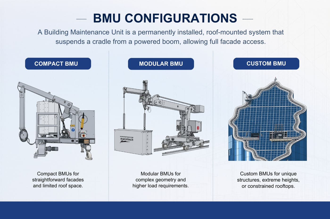
Facade Access Solutions offers three BMU configurations:
Compact BMUs typically service buildings up to approximately 150 m. Modular BMUs extend coverage to approximately 300 m. Custom multi-stage drum-hoist BMUs are engineered for supertall buildings. Alimak Group brands have delivered systems on landmark projects including the Burj Khalifa (828 m), Merdeka 118 (679 m), and Shanghai Tower (632 m).
Safety is fully integrated into system design. Cradles are typically suspended on a working rope plus an independent secondary safety rope at each suspension point — so a twin-suspension cradle commonly runs four lines (two working + two safety). The exact configuration depends on cradle length, SWL, and EN 1808 redundancy provisions.
Davit systems provide a cost-effective permanent access solution using fixed rooftop bases and portable davit arms.
In operation, the davit boom rotates over the parapet, while a suspended platform travels along the boom via a trolley system.
Powered davit carriages improve efficiency by moving along a roof track system. This removes manual repositioning and allows faster deployment across larger buildings. These systems can service structures up to 200 metres.
Davit systems also support multiple configurations, including work cages and bosun chairs, making them adaptable across different maintenance tasks.
Selecting the right facade access system is not a single-variable decision. It requires a structured assessment of building height, facade geometry, frequency of access, and compliance obligations. Each factor influences not only the type of system that can be installed, but also how effectively it will perform over the building’s lifecycle.
A solution that appears cost-effective at specification stage may introduce operational inefficiencies, increased labour requirements, or compliance risks once the building is in use. For this reason, system selection should be approached as part of the building’s long-term asset strategy rather than a short-term construction decision.
In practice, this means evaluating how the system will be used over time, not just how it is installed. Buildings with complex geometries or frequent maintenance cycles benefit from fully integrated systems that reduce setup time and improve access consistency.
At the same time, regulatory requirements such as anchor placement and load capacity must be designed into the structure early. Engaging facade access specialists during the design phase ensures the selected system is technically viable, compliant, and aligned with long-term operational efficiency.
Building height sets the baseline for selecting the appropriate access system. For buildings up to approximately 15 to 18 metres, mobile elevating work platforms such as boom lifts or scissor lifts may be sufficient for construction-phase access and light maintenance.
Once a building exceeds this range — especially for mid-rise or high-rise structures in regular use — a permanent facade access system becomes necessary.
Complexity must be evaluated alongside height. A six-storey building with deep recesses, stepped setbacks, or overhangs may require a monorail or custom BMU, while a taller building with a flat facade may not. Both height and geometry must be assessed together to ensure complete and safe access.
Facade geometry determines how access must be delivered once system type is broadly defined. A flat facade with a consistent parapet is the simplest condition and can typically be serviced by a compact BMU operating on a horizontal track system.
This setup allows efficient coverage with minimal system complexity.
As geometry becomes more complex, access solutions must adapt. Curves, overhangs, setbacks, fins, and recesses require systems that can safely reach or follow these features, including telescopic jibs, articulating platforms, or curved tracks.
For interior atria or enclosed spaces, monorails are often required.
The frequency of facade maintenance directly impacts system selection and long-term efficiency. For buildings that require access only once or twice a year, a davit system paired with a self-powered cradle is often the most economical permanent solution.
These systems are lightweight, require minimal rooftop infrastructure, and have low visual impact when not in use.
For buildings with frequent maintenance cycles, such as regular cleaning or inspections, a fully tracked BMU system offers greater efficiency. It reduces setup time, eliminates manual repositioning, and enables faster, more consistent coverage.
Over time, the higher upfront investment can result in lower operational costs.
Compliance is a structural requirement that directly affects which systems can be specified and installed. Key standards include EN 1808, OSHA 29 CFR 1926, and CAN/CSA-Z271 and Z91, alongside local codes depending on project location.
These regulations define safety requirements, system design parameters, and operational constraints for facade access equipment.
For buildings above 40 metres, intermittent stabilisation anchors must be integrated into the facade when suspended platforms are used. These requirements must be incorporated during design, as retrofitting is complex and costly.
Proper planning ensures systems are compliant, safe, and aligned with long-term building performance.
Facade Access Solutions supports project teams through an IDS-led approach that integrates facade access requirements early in the building design process.
With over 16,000 systems installed globally and engineering teams across key regions, the company provides integrated design support (IDS) from concept development and system specification through installation and long-term lifecycle service.
The portfolio includes BMUs, davit systems, monorails, self-powered suspended platforms, and fall protection systems, ensuring coordinated facade access solutions for a wide range of building types and maintenance requirements.
Contact the team to discuss your facade access requirements.
BMU design is not a downstream decision. It is a core part of how a building is engineered, accessed, and maintained over its entire lifecycle.
When building maintenance unit design is addressed late, the consequences are immediate and costly. Structural retrofits become unavoidable. Facade access is compromised. Compliance risks increase. What should have been an integrated system becomes a constraint.
For architects, engineers, and developers, BMU design extends far beyond equipment selection. It defines how mechanical systems interact with the building structure and how access is achieved across every section of the facade. Jib configuration, hoist selection, traversing systems, and platform design must align with roof load capacity, parapet conditions, and architectural intent from the outset.
Building height, facade geometry, and roof configuration directly determine the BMU strategy. At the same time, compliance with standards such as EN 1808, OSHA 1910.66, ASME A120.1, and AS/NZS 1418.13:2013 must be embedded into the design. These are not final-stage checks. They are engineering constraints that shape the system from day one.
Effective BMU design sits at the intersection of structural engineering, mechanical systems, and architecture. These disciplines must be resolved together to ensure safe operation and full facade coverage.
A well-engineered BMU begins with a clear understanding of the building.
Building height determines hoist configuration and rope length. For structures above 125 metres, multi-layer drum hoists are typically required. Modular and custom BMUs with multi-layer drum hoists service buildings well beyond 300 m. Multi-stage configurations have been deployed on the Burj Khalifa (828 m), Merdeka 118 (679 m), and Shanghai Tower (632 m).
Facade complexity dictates jib configuration. Uniform facades may require only a fixed arm, while recessed, stepped, or curved geometries demand telescopic, luffing, or articulated designs.
Roof structure defines the system type. Load-bearing roofs support track systems, while non-load-bearing roofs require parapet-mounted solutions. Concrete runway systems provide an alternative where track installation is not viable.
Available roof space affects parking and concealment strategy. Whether the BMU is stored openly, within a garage, or in a recessed pit must be considered early.
Facade coverage requirements determine whether a single BMU is sufficient or if additional systems are needed.
EN 1808:2015 §6.1.2.5 specifies a minimum static safety factor of 12 on each suspension rope (i.e. rope MBL ≥ 12 × maximum static rope tension). This drives rope diameter selection — typically 7–14 mm depending on cradle length, payload, and reeving. In North America OSHA and CSA require suspension wire ropes to respect a safety factor of 10:1.
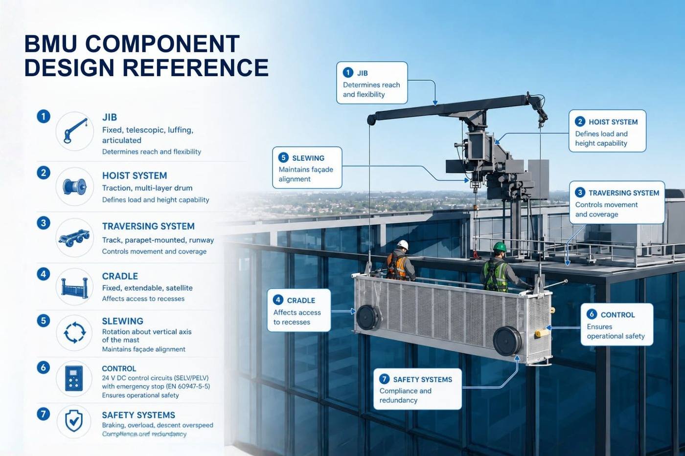
A BMU is a fully configured system. Each component defines façade coverage, safety, and integration with the building.
| Component | Key Options | Design Impact | When to Use |
|---|---|---|---|
| Jib | Fixed, telescopic, luffing, articulated | Determines reach and flexibility | Telescopic/articulated for complex facades |
| Hoist System | Traction, multi-layer drum | Defines load and height capability | Drum hoists for tall buildings |
| Traversing System | Track, parapet-mounted, runway | Controls movement and coverage | Parapet/runway for constrained roofs |
| Cradle | Fixed, extendable, satellite | Affects access to recesses | Extendable/satellite for complex facades |
| Slewing | Rotation about vertical axis of the mast | Maintains facade alignment | Required for corners and curves |
| Control | Control circuits operate at extra-low voltage (typically 24 V DC) in line with EN 1808’s SELV/PELV requirement. Emergency-stop functions with positive-opening contacts (EN 60947-5-5) are mandatory. | Ensures operational safety | Standard across all systems |
| Safety Systems | Braking, overload, descent overspeed | Compliance and redundancy | Mandatory under EN/OSHA |
The jib determines how the BMU interacts with the facade and whether full access can be achieved.
| Facade Condition | Recommended Jib Type | Reason |
|---|---|---|
| Moderate recesses | Telescopic jib | Adjustable outreach |
| Sloped roofs | Luffing jib | Vertical clearance capability |
| Complex geometry | Articulated jib | Multi-point flexibility |
| Highly complex structures | Telescopic + rotating hoist | Maximum access capability |
Fixed jibs suit simple facades, while telescopic and articulated designs allow the system to adapt to complex geometries. Luffing jibs introduce vertical movement, enabling the arm to clear architectural elements. A slewing head ensures the cradle remains parallel to the facade during operation.
The hoist defines vertical movement and operational limits. Personnel cradle SWL is capped at 1,000 kg under EN 1808. Standard configurations support 240–500 kg; modular cradles reach 1,000 kg. Material-only hoists (governed by EN 14492-1 rather than EN 1808) extend beyond personnel limits when separate equipment-lifting use cases are designed in.
Typical operational lifting speeds are 9–11 m/min, well within the 18 m/min ceiling EN 1808 §5.3.7 sets for permanently installed cradles. Traversing speeds typically range 10–15 m/min.
Traversing systems determine how the BMU moves across the building.
Horizontal tracks are the most common where roof space allows. Parapet-mounted systems transfer loads to the building edge and suit non-load-bearing roofs. Concrete runway systems operate without tracks, using wheeled movement across a load-bearing surface.
Shunting systems allow the BMU to move into garages or concealed positions. For sloped or curved roofs, inclined or rack-and-pinion systems with self-levelling ensure stability.
The cradle is the working platform, typically constructed from aluminium with integrated safety systems.
Cradles are typically suspended on a working rope plus an independent secondary safety rope at each suspension point — so a twin-suspension cradle commonly runs four lines (two working + two safety). The exact configuration depends on cradle length, SWL, and EN 1808 redundancy provisions.
Extendable platforms and satellite cradles improve access across complex facades. Slewing functionality ensures alignment with the facade, while safety features such as braking and controlled descent are mandatory under EN 1808 and ASME standards.
Selecting the right BMU design prevents both over-engineering and under-specification.
| Design Factor | Compact BMU | Crane-Type BMU | Modular / Custom BMU |
|---|---|---|---|
| Building Height | Up to 270 m | Up to 270 m | 270 m+ |
| Facade Complexity | Simple | Moderate | Complex |
| Jib Type | Fixed/basic | Slewing | Telescopic/articulated |
| Reach | Limited | Moderate | High |
| Roof Constraints | Low | Moderate | Flexible |
| Load Capacity | 240–500 kg | 240–500 kg | Up to 4,200 kg |
| Best Use | Standard buildings | Buildings with obstructions | Iconic or high-rise buildings |
Modern BMU design incorporates concealment strategies to minimise visual impact.
| Method | How It Works | Design Requirement | Best For |
|---|---|---|---|
| Parking Pit | Retracts below roof | Structural integration | Zero visibility |
| Garage | Enclosed storage | Space and clearance | Concealed systems |
| Integrated | Built into structure | Early collaboration | Design-led buildings |
| Track Concealment | Hidden behind parapet | Precise positioning | Low visibility |
| Curved Traversing | Moves along facade | Custom track design | Curved buildings |
Parking pits and garages provide full concealment, while integrated solutions embed the BMU into the building structure. These approaches require early coordination between design disciplines.
Curved and irregular facades require specialized engineering. Track systems must follow building geometry, supported by self-levelling and pivoting mechanisms.
Advanced systems allow multi-directional movement, ensuring safe operation across complex surfaces.
Visibility is controlled through system height, positioning, and colour matching. Compact BMUs are designed to sit below parapet level, minimizing visual impact.
Late-stage BMU decisions lead to avoidable constraints. Early IDS integration ensures proper system coordination, compliance, and full facade coverage.
Facade Access Solutions delivers integrated design support (IDS) from early-stage planning through installation and lifecycle service. With over 16,000 systems installed globally and engineering teams across key regions, the company delivers proven expertise across complex projects.
Engage IDS planning early to ensure efficient integration, compliance, and long-term facade access performance.
Facade access systems fall into several broad categories, each suited to a different building height, facade geometry, and maintenance requirement. For mid-rise and high-rise buildings, these systems are essential to support safe and efficient facade cleaning, inspection, and repair.
From permanent Building Maintenance Units (BMUs) to davit systems, monorails, suspended platforms, rope access, and supporting systems, each solution plays a distinct role in building facade cleaning and long-term maintenance planning. The right system depends on structural design, access frequency, and operational demands. This article covers all major categories and outlines the structural, regulatory, and design factors that influence selection.
Facade access systems directly affect worker safety, regulatory compliance, and long-term maintenance cost. Failing to integrate an appropriate system during the design phase often leads to non-compliance, unsafe temporary solutions, or expensive retrofits later in the building lifecycle.
In many regions, buildings above certain height thresholds are legally required to include permanent facade access systems. These systems significantly reduce risk by incorporating engineered safety mechanisms such as dual-line suspension, stabilization, and controlled operation. They also ensure complete coverage for external facade cleaning, eliminating maintenance gaps that can lead to long-term deterioration or warranty issues.
Facade access systems fall into two primary categories: permanent and temporary. Permanent systems, including BMUs, monorails, davit base networks, and tieback anchors, are integrated into the building and available year-round. They require periodic inspection and certification, rather than repeated setup approvals, making them more efficient over time.
Temporary systems, such as mobile elevated work platforms, scaffolding, outrigger, and rope-based setups, are installed per job and must be recertified before each use. While useful for short-term tasks, they are less efficient for buildings requiring regular commercial facade cleaning or inspection.
For most mid-rise and high-rise buildings, permanent systems provide better compliance, improved safety, and lower lifecycle cost.
A permanent facade access system becomes necessary based on several key factors. Building height is the primary driver.
Facade complexity is another critical consideration. Buildings with curved, recessed, or cantilevered designs typically require engineered access solutions that temporary systems cannot safely accommodate. Frequency of maintenance also plays a role, as buildings requiring regular cleaning or inspection benefit from systems that are always ready for use. In addition, many facade contractors require a permanent access system before issuing warranties, making early integration essential.
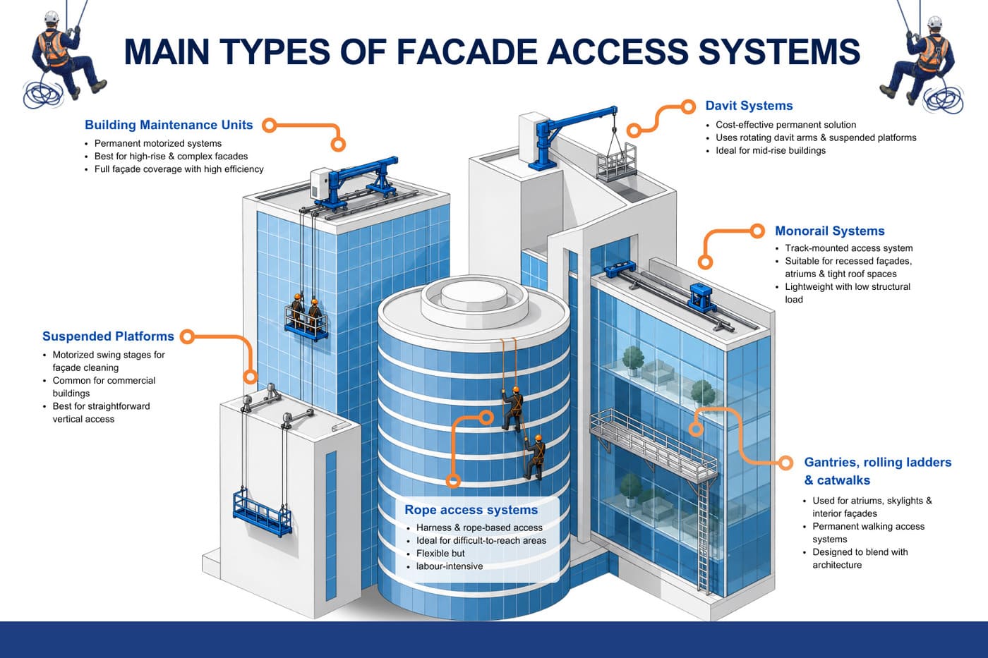
Facade access systems range from large, permanently installed motorized units to lightweight track-based systems, davit, monorail and rope-based solutions. These systems support a wide range of applications, from routine building facade cleaning services to complex inspection and repair tasks. Each system has distinct capabilities, structural requirements, and operational advantages.
A Building Maintenance Unit is a permanently installed, motorized system that allows a suspended platform to travel vertically and horizontally across a building facade. BMUs are the standard solution for high-rise and complex buildings, offering full coverage and efficient operation.
Facade Access Solutions, part of Alimak Group, has delivered BMU systems on landmark projects including the Burj Khalifa, Shanghai Tower, and Merdeka 118 through its CoxGomyl and Manntech brands.
Compact BMUs are designed for buildings with simple facades and limited roof space. They operate on roof tracks or concrete runways and offer low visual impact while remaining easy to maintain.
Modular BMUs provide greater flexibility for mid-rise to high-rise buildings with more complex geometry. Their configurable design allows adjustments without requiring full system replacement.
Custom and telescopic roof cars are engineered for architecturally complex or supertall buildings. These systems can include telescoping arms, articulating platforms, and concealed parking solutions that integrate with the building design.
Davit systems are a traditional and cost-effective solution for facade cleaning equipment in permanent installations. They consist of fixed bases, rotating davit arms, suspended platforms, and safety lifelines.
Portable davit arms are a cost-effective solution typically used on buildings up to ~90 m (300 ft), where manual repositioning is operationally acceptable. With powered davit carriages on roof tracks, the same equipment family can service high-rise buildings when properly engineered for the project requirements.
Powered davit carriage systems eliminate manual repositioning by allowing the davit system to travel along a fixed track. This significantly improves efficiency for mid-rise and high-rise buildings with frequent maintenance needs.
Monorail systems use a track mounted along the building facade or roofline, allowing a trolley and suspended platform to move horizontally. These systems are particularly effective for buildings with recessed facades, atriums, or areas inaccessible to roof-mounted equipment.
Standard monorail tracks are lightweight and impose minimal structural load. Advanced configurations can include intersections to expand coverage.
Climbing monorail systems allow movement along inclined or curved surfaces, making them suitable for complex architectural designs such as sloped roofs or glazed atriums.
Suspended platforms, also known as swing stages, are motorized cradles supported by roof-mounted systems. They are widely used for external facade cleaning across commercial buildings.
These platforms typically support two operators and allow vertical movement along the facade. However, horizontal repositioning requires detachment and repositioning before use, making them less efficient for large or complex structures. For taller buildings, BMUs or powered davit systems are generally more suitable.
Rope access systems allow technicians to ascend and descend a building facade using harnesses and ropes secured to structural anchors. Rope access friendly systems can be designed utilizing tieback placement conducive to application and design or rope access procedures.
These systems are best suited for short-duration tasks or difficult-to-reach areas. Labour-intensive operation can lead to higher long-term costs compared to permanent systems.
Gantries, rolling ladders, and catwalks are specialized systems used for accessing glass roofs, atriums, and interior facades. Gantries move along tracks and allow safe walking access, while rolling ladders provide angled positioning for maintenance work.
Catwalks are permanent walkways integrated into the building structure, enabling safe inspection and light maintenance. These systems are typically designed to align with architectural aesthetics while supporting safe access.
The most effective approach is to utilize FAS Integrated Design Service (IDS) or involve a facade access specialist early in the design process. This ensures that structural requirements, roof loads, and system integration are considered from the outset. The following factors determine the most appropriate solution.
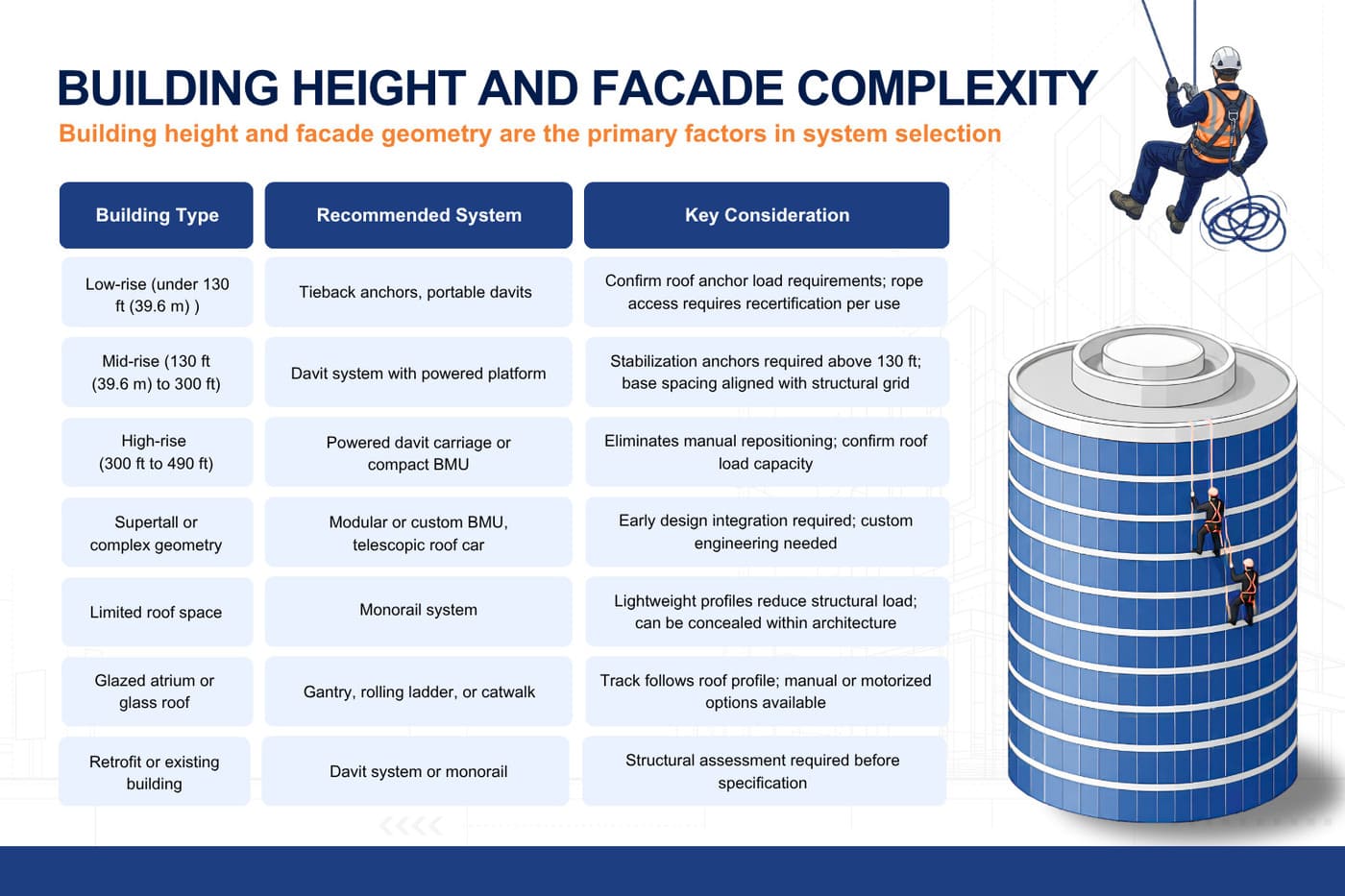
Building height and facade geometry are the primary factors in system selection.
| Building Type | Recommended System | Key Consideration |
|---|---|---|
| Low-rise (under 130 ft (39.6 m)) | Tieback anchors, portable davits | Confirm roof anchor load requirements; rope access requires recertification per use |
| Mid-rise (130 ft (39.6 m) to 300 ft) | Davit system with powered platform | Stabilization anchors required above 130 ft; base spacing aligned with structural grid |
| High-rise (300 ft to 490 ft) | Powered davit carriage or compact BMU | Eliminates manual repositioning; confirm roof load capacity |
| Supertall or complex geometry | Modular or custom BMU, telescopic roof car | Early design integration required; custom engineering needed |
| Limited roof space | Monorail system | Lightweight profiles reduce structural load; can be concealed within architecture |
| Glazed atrium or glass roof | Gantry, rolling ladder, or catwalk | Track follows roof profile; manual or motorized options available |
| Retrofit or existing building | Davit system or monorail | Structural assessment required before specification |
Facade geometry further influences system choice. Buildings with curves, setbacks, or irregular profiles often require custom-engineered solutions or a combination of systems to achieve full access coverage.
Buildings with frequent cleaning schedules benefit from permanent systems that minimize setup time and operational cost. Systems used for building facade cleaning services on a weekly or monthly basis must be efficient and easily deployable.
Buildings with lower maintenance frequency may rely on simpler systems, but lifecycle cost should always be considered. Davit systems and anchor networks also provide flexibility for multiple maintenance functions, including inspections and repairs.
Each facade access system imposes specific loads on the building structure. These loads must be validated by a structural engineer during the design phase.
Davit systems apply localized loads at base points, while BMUs can weigh several tons depending on configuration. Monorail systems offer a lower-load alternative and are often used where roof capacity is limited.
For retrofit applications, all mounting methods must be carefully assessed to ensure compatibility with the existing structure.
All facade access systems must comply with applicable safety standards. In North America, this includes OSHA and local regulations, while Canada follows CSA standards and Europe adheres to EN 1808.
Permanent systems require a periodic inspection by a competent person under OSHA 1910.66(g)(2), EN 1808 §9, and ASME A120.1 §10. Load testing is performed at commissioning and after any modification, repair affecting the load path, or relocation — not annually.
Facade Access Solutions, part of the Alimak Group, has over 80 years of experience and more than 16,000 systems installed worldwide. With engineering teams across Germany, Spain, Luxembourg, Toronto, Dubai, and Singapore, the company supports projects from early design through to installation, ensuring compliance and long-term performance. We also offer Integrated Design Services (IDS) which will help with design of the safest, most practical and economical solution. Ask about out IDS services.
Explore our full range of facade access systems.
Speak to a Facade Access Solutions engineer about your building.
On any commercial or high-rise building, tieback anchors are not optional accessories. They are the structural link between workers, equipment, and a safe working system. Without correctly specified and load-rated anchor points, every suspended access task introduces avoidable risk.
Despite this, tieback anchors are often treated as secondary components rather than engineered systems. This is where gaps in safety, compliance, and long-term performance begin.
This guide explains what tieback anchors for fall protection are, how they function within facade access systems, and how to specify them correctly. It covers mounting methods, load requirements, and key compliance standards including OSHA, ANSI/IWCA, and CSA Z91. It also outlines how tieback anchors integrate with davit systems, lifelines, and fall arrest applications.
Facade Access Solutions supplies and installs the full range of tieback anchors as part of a complete building access strategy.
A tieback anchor, also known as a safety anchor, roof anchor point, U-bar anchor, or fall arrest anchor, is a permanent structural attachment point installed on a building’s roof, parapet, or facade. It is designed to secure workers and building maintenance equipment against uncontrolled movement or fall.
As part of the building structure, its performance depends on correct specification, load capacity, and structural integration.
In practice, tieback anchors serve two core functions. They provide personal fall arrest for workers using lanyards or lifelines, and they secure equipment such as davit arms and outrigger beams. These two roles work together to maintain both worker safety and system control.
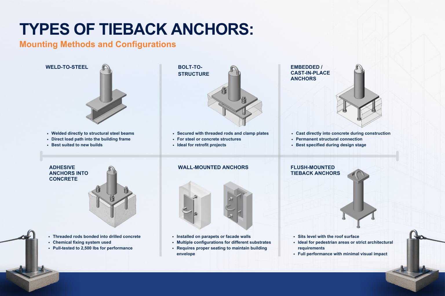
The need for tieback anchors is defined by building use and applicable safety standards.
In the United States, OSHA 29 CFR 1910.66 governs powered platforms on building exteriors, while ANSI/IWCA I-14.1 provides detailed requirements for anchor placement and system design. In Canada, CSA Z91 establishes similar standards for suspended equipment and anchor systems.
These regulations determine not only when anchors are required, but also how they must be positioned to ensure safe operation.
Load requirements vary depending on how the anchor is used, but all configurations must meet minimum performance standards defined by applicable codes. These values define the baseline requirement. In all cases, structural verification is required to confirm the building can safely support the applied loads.
With load requirements established, the next step is selecting the appropriate mounting method. This is the most important specification decision, as it determines how loads are transferred into the building structure. The correct choice depends on the substrate, the stage of the project, and the installation location.
Facade Access Solutions provides a full range of mounting options designed to match these conditions.
Once the mounting method is defined, the focus shifts to how tieback anchors function within the wider access system. Tieback anchors are not standalone components. They form part of a coordinated system that enables safe and efficient facade access over the life of the building.
They support worker safety at rooftop level, secure access equipment, and contribute to safe maintenance operations.
With a clear understanding of mounting methods and system integration, specification decisions can be aligned to the building itself.
The correct approach depends on the structure, height, and maintenance requirements. Early coordination is key to avoiding costly changes later.
For new high-rise buildings, anchors should be integrated into the structural design. Embedded or weld-to-steel systems are typically used, supported by stabilization anchors and coordinated access equipment.
In retrofit scenarios, flexibility becomes the priority. Bolt-on, adhesive, and wall-mounted anchors are selected based on existing conditions, with testing and verification ensuring compliance.
Architecturally sensitive projects often require flush-mounted systems to maintain visual consistency. Industrial and infrastructure projects, on the other hand, may require custom-engineered solutions to address non-standard conditions.
In all cases, early engagement ensures that anchor systems are aligned with both structural and operational requirements.
Every effective tieback anchor specification comes down to three decisions: selecting the correct mounting method, ensuring the appropriate load rating, and integrating the anchor into the wider access system.
These are permanent installations. Their performance affects not only immediate safety, but also long-term maintenance and compliance.
Facade Access Solutions designs, supplies, and installs the full range of tieback anchors across commercial, high-rise, and industrial projects worldwide. With over 16,000 systems installed across 39 locations, the company delivers proven expertise from design through installation.
For project-specific guidance, the team can support your anchor specification from early design to final implementation.
At height, facade maintenance becomes a controlled engineering operation rather than a routine task. Workers are suspended hundreds of metres above ground, operating across complex geometries that include setbacks, curved curtain walls, and constrained rooftops. In these conditions, safety is not dependent on operator judgement alone. It is defined by the design, redundancy, and performance of the access system itself.
A BMU system is engineered to meet these demands. Unlike temporary solutions that rely on site conditions and manual setup, modern Building Maintenance Units are permanently integrated into the building’s structure. Permanently installed BMUs must comply with applicable standards based on system type, with OSHA requirements applied where relevant and EN 1808 governing suspended access equipment in European projects. This article examines how modern building maintenance unit system safety is achieved, the engineering principles behind it, and how it supports safe, consistent, and compliant high-rise facade maintenance.
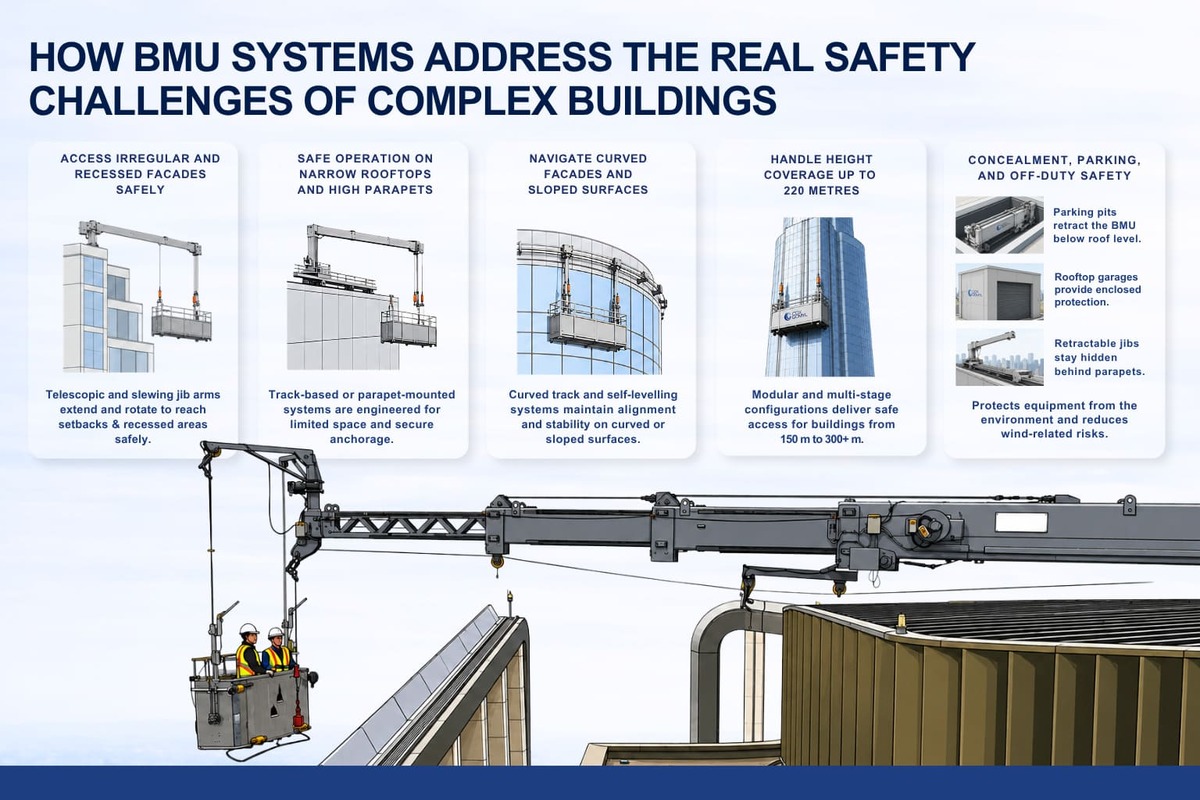
A BMU system is a permanent mechanical access solution installed on a building to support facade cleaning, inspection, and maintenance. It is engineered specifically for the structure it serves, which means safety is integrated from the earliest design stage rather than added later. The system is made up of several interconnected components that work together to ensure safe operation. A roof-mounted BMU or track system enables horizontal movement across the building, while a telescopic or luffing jib positions the platform precisely where it is needed. The suspended platform carries workers and equipment, supported by independent galvanized steel wire ropes, and all movements are controlled through an operator panel that allows precise positioning. Steel components are protected by hot-dip galvanizing, multi-layer painting systems, or stainless steel depending on environmental exposure. Marine, coastal, and high-pollution environments require specific attention.
Each of these elements has a defined safety function. Platforms are typically suspended on a working rope plus an independent secondary safety rope at each suspension point, so a twin-suspension platform commonly runs four lines: two working ropes and two safety ropes. The exact configuration depends on platform length, rated working load (SWL), and the redundancy provisions defined by governing standards. This level of design ensures consistent stability, even in high-risk environments.
Modern architecture rarely follows simple geometry. Facades often include setbacks, curves, recessed sections, and varying elevations, while rooftops may present limited space or structural constraints. These conditions create access challenges that temporary systems cannot safely handle.
A well-designed building maintenance unit safety system addresses these challenges through engineered movement, controlled positioning, and building-specific configuration.
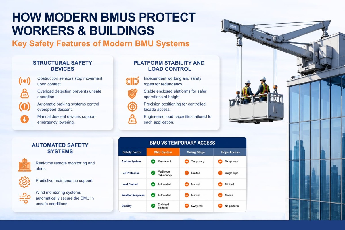
Safety in a BMU system is achieved through multiple layers of protection working together rather than relying on a single feature.
Modern BMU systems incorporate built-in safeguards designed to prevent incidents before they occur. Obstruction sensors detect contact with the facade and immediately stop movement to avoid damage or instability. Overload detection systems prevent operation when the platform exceeds its rated capacity, ensuring that load limits are never compromised. Additional safety mechanisms include centrifugal brakes that activate automatically during overspeed descent and electromagnetic brakes that hold the platform securely in position when not in motion. In the event of a power failure, manual descent devices allow operators to lower the platform safely to ground level.
Platform stability is central to safe operation at height. BMU platforms are suspended using a working rope with an independent secondary safety rope at each suspension point. In twin-suspension configurations, this typically results in four lines. Across Facade Access Solutions systems, rated working loads typically range from 240 kg to 1,000 kg, depending on the application. Rope diameters vary accordingly, ensuring that each system is tailored to its specific requirements. The addition of slewing functionality allows operators to adjust the platform position with precision, maintaining alignment with the facade without needing to reposition the entire system.
Modern BMU systems are defined by their advanced digital capabilities. Remote monitoring allows facilities managers to track system performance in real time, receive alerts, and plan maintenance proactively. Wind monitoring systems add another layer of protection by automatically stopping operation and securing the system when conditions exceed safe limits. This removes reliance on operator judgement during changing weather conditions and ensures a consistent safety response.
While temporary access methods may appear cost-effective initially, they introduce greater long-term safety risks and operational limitations.
| Safety Factor | BMU System | Swing Stage | Rope Access |
|---|---|---|---|
| Anchor System | Permanent, engineered | Temporary rigging | Temporary anchors |
| Fall Protection | Multi-rope redundancy | Limited | Single rope |
| Load Control | Automated | None | Minimal |
| Weather Response | Automated | Manual | Manual |
| Stability | Enclosed platform | Sway risk | No platform |
| Coverage | Full facade | Limited | Limited |
Swing stages rely heavily on manual setup and judgement, while rope access is limited in both load capacity and positioning control, particularly on complex facades. A BMU system provides a stable, enclosed working environment with integrated safety features and consistent performance.
Not every building requires the same solution. The right BMU system depends on height, facade complexity, rooftop configuration, and maintenance requirements. Buildings with standard facades and moderate height can benefit from compact or economical systems that offer reliable access with straightforward installation. More complex structures, particularly those with irregular geometry or significant height, require modular systems that provide greater flexibility and reach. Where architectural appearance is a priority, concealed parking solutions allow the system to remain hidden when not in use. For retrofit projects, structural feasibility assessments are essential to ensure that the building can safely support the system. Facade Access Solutions supports this process through integrated design services, ensuring that each system is engineered to meet both safety and operational requirements.
Facade Access Solutions has delivered more than 16,000 systems worldwide and operates across 39 locations. Its engineering teams support projects globally, including some of the most demanding high-rise developments. Facade access is not a secondary consideration. It is a critical component of building safety and long-term performance. From early design consultation through to installation and ongoing service, Facade Access Solutions provides a complete lifecycle approach to facade access systems.
Contact the team to discuss your facade access and safety requirements.
Disclaimer: Graphics shown are illustrative only and do not represent actual products, equipment, or real-life conditions.
Selecting the correct standard ladder dimensions is not just a design choice. In commercial, industrial, and high-rise environments, it is a critical safety and compliance requirement. Incorrect ladder width, spacing, or configuration can lead to failed inspections, operational delays, and serious risks to workers.
For architects, engineers, and facilities managers, ladder specifications must support a broader building access strategy. This means aligning ladder dimensions with global safety standards, site conditions, and long-term maintenance requirements.
This guide covers ladder width standards, dimensional requirements by ladder type, and how to choose the right ladder system for safe, compliant, and efficient access.
Understanding ladder width standards across regions is essential for ensuring compliance and avoiding redesigns. Many commercial projects require alignment with multiple regulations, particularly in global developments.
In the United States, OSHA defines the baseline for ladder safety compliance. Fixed ladders must have a minimum clear width of 16 inches (41 cm), while portable ladders must be at least 11.5 inches (29 cm) wide. Updated OSHA regulations also require ladders above 24 feet to include ladder safety systems or personal fall arrest systems. Safety cages are no longer accepted as the sole protection method, and all replacements before 2036 must comply with these updated requirements.
ANSI standards expand on OSHA by defining ladder load ratings and performance classes. Light-duty ladders require a minimum width of 11.5 inches, while heavy-duty applications require 12 inches or more. These classifications directly influence ladder design, durability, and load capacity.
Across Europe, EN 131 introduces usability requirements. Portable ladders must have a minimum width of 280 mm (11 inches), while platform ladders require a minimum standing area of 400 mm (16 inches).
In Australia and New Zealand, AS/NZS 1892 governs ladder design across materials and applications, with requirements varying by ladder type. Other global standards include CSA Z11 in Canada, which aligns with ANSI, and GB/T 17889 in China, which links ladder dimensions to load capacity. In the Middle East, projects typically reference OSHA, EN, or British Standards.
These frameworks show that standard ladder width is not universal. It must be selected based on region, application, and integration with safety systems.
Regulation |
Region |
Portable Ladder Min. Width |
Fixed Ladder Min. Width |
Platform Ladder Min. Width |
| OSHA 1910 / 1926 | United States | 11.5 in (29 cm) | 16 in (41 cm) | 16 in (41 cm) |
| ANSI A14 Series | United States | 11.5 in (29 cm) | 16 in (41 cm) | 12+ in (30+ cm) |
| EN 131 | Europe (EU) | 280 mm (11 in) | Per national annex | 400 mm (16 in) |
| AS/NZS 1892 | Australia / NZ | Verify by type | Per AS/NZS 1892.4 | Verify by type |
| GB/T 17889 | China | Per national standard | Per national standard | Per national standard |
| CSA Z11 | Canada | Similar to ANSI | Similar to ANSI | Similar to ANSI |
While regulations define minimum requirements, selecting the right ladder type ensures safe access, usability, and long-term performance. Each ladder type has specific ladder dimension requirements that must match the working environment.
Step ladders are self-supporting and commonly used for indoor maintenance tasks. Typical step ladder dimensions include a width of 12 to 20 inches and rung spacing between 10 and 12 inches. They are ideal for painting, lighting adjustments, and general facility work where mobility and compact design are essential.
Extension ladders are designed for vertical reach in construction and facade access. Standard extension ladder dimensions range from 14 to 18 inches in width, with rung spacing of 12 inches. For safe use, the ladder must extend at least 3 feet above the landing, follow a 4:1 angle ratio, and be placed on a stable base. These ladders are widely used for roof access, inspections, and temporary facade work.
Fixed ladders are a key component of roof access systems and facade maintenance strategies. Standard fixed ladder dimensions include a minimum width of 16 inches, rung spacing between 10 and 14 inches, at least 7 inches of stand-off clearance, and grab bars extending 42 inches above the landing. Access width through the ladder typically ranges from 24 to 30 inches.
For ladders exceeding 24 feet, fall protection systems are mandatory, and safety cages can no longer be used as the only protection method. These ladders are commonly integrated with BMUs, monorails, and rooftop equipment.
Platform ladders are designed for stability and worker comfort. Standard platform ladder dimensions range from 16 to 22 inches in width, providing a secure standing area for detailed tasks such as electrical work and inspections.
Industrial ladders are built for high-frequency use in demanding environments. Typical industrial ladder dimensions range from 20 to 30 inches in width, allowing for greater stability and load capacity. OSHA requires these ladders to support at least four times their intended load and to include handrails and stable rolling mechanisms.
Multi-position ladders offer flexibility across multiple configurations. Standard multi-position ladder dimensions range from 18 to 24 inches in width, making them suitable for uneven terrain, stairways, and renovation projects.
Ladder Type |
Typical Width |
Rung Spacing |
Height Range |
Load Rating |
Best Applications |
| Step Ladder | 12–20 in | 10–12 in | 4–14 ft | Type II–IA | Interior maintenance, painting |
| Extension Ladder | 14–18 in | 12 in | 16–40 ft | Type I–IA | Roof access, construction |
| Fixed Ladder | 16+ in | 10–14 in | Custom | Custom | Permanent building access |
| Platform Ladder | 16–22 in | 10–12 in | 4–16 ft | Type IA–IAA | Prolonged tasks, electrical work |
| Industrial/Rolling | 20–30 in | ≤10 in rise | 4–20 ft | Type IAA (375+ lbs) | Warehouses, facade maintenance |
| Multi-Position | 18–24 in | 12 in | 6–22 ft | Type IA | Stairways, uneven terrain |
Ladder width directly impacts stability, load capacity, and worker safety. Wider ladders distribute weight more effectively, reducing the risk of tipping in professional environments.
As a general rule, each additional inch of ladder width can increase load capacity by approximately 20 to 30 pounds. For example, a 16-inch ladder rated at 300 pounds offers significantly more stability than a 12-inch ladder rated at 200 pounds. In most commercial applications, a width of around 18 inches is recommended to allow safe movement, especially when workers use tools or wear PPE.
Environmental conditions also influence ladder selection. Wet or corrosive environments require slip-resistant materials, while confined spaces may require narrower ladders supported by additional safety systems.
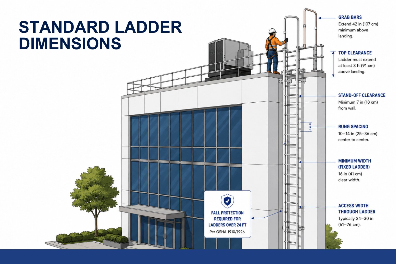
Choosing the right ladder dimensions depends on application, environment, and frequency of use. In commercial and industrial facilities, wider ladders of 20 inches or more are often preferred for stability and repeated access. In high-rise buildings, fixed ladders typically range from 16 to 20 inches and must integrate with facade access systems.
Ladders exceeding 24 feet must include compliant fall protection systems, while all ladder designs should align with rooftop equipment such as BMUs, davits, and monorails. Construction environments must meet OSHA requirements, while confined spaces may require more compact solutions with additional safety controls.
Ladders are only one element of a complete building access system. They must integrate with fall protection systems, monorails, davits, and facade access equipment to ensure safe and efficient maintenance.
Fixed ladders provide access to rooftops and service areas, while BMUs enable full facade coverage. Proper coordination between these systems improves safety, reduces operational risk, and supports long-term maintenance efficiency.
Early collaboration between architects, engineers, and facade access specialists helps ensure compliance and prevents costly design changes later in the project.
Selecting the correct standard ladder dimensions ensures safe, compliant, and efficient building operations. Every detail, from width and rung spacing to clearance and fall protection, plays a role in long-term performance.
To achieve the best results, project teams should go beyond minimum standards and consider how ladders will be used over time. Integrating ladder systems with complete access solutions ensures better safety, smoother operations, and reduced lifecycle costs.
Facade Access Solutions APAC provides end-to-end expertise in ladder systems, facade access, and integrated building access design.
Contact our team today to discuss your project requirements and ensure full compliance with global ladder standards.
Disclaimer: Graphics shown are illustrative only and do not represent actual products, equipment, or real-life conditions.
Infrastructure Access Solutions, part of Alimak Group, was engaged to undertake a major inspection and engineering assessment of the powered under-deck gantries operating beneath the Sydney Harbour Bridge. These permanent access systems enable inspection and maintenance crews to safely access the bridge’s steelwork below the roadway, a critical component in maintaining one of Australia’s most iconic pieces of infrastructure.
The project required detailed engineering assessment of complex access plant operating in a highly constrained environment beneath an active transport corridor. The gantries consist of integrated structural, mechanical, electrical, and control systems that must function reliably while supporting suspended access operations at height.
Working within strict safety and operational requirements, the inspection program needed to verify the integrity and performance of the systems while minimizing disruption to ongoing maintenance activities.
Infrastructure Access Solutions delivered a coordinated major inspection and certification program, combining in-house engineering expertise with specialist testing services.
The scope included comprehensive inspection of structural elements, drive systems, rolling components, electrical and control systems, and operator safety features. Non-destructive testing of critical components was undertaken through a NATA-accredited laboratory, alongside functional testing of brakes, limit systems, and operational controls.
Infrastructure Access Solutions managed multiple specialist disciplines throughout the project, ensuring a structured inspection methodology and clear engineering documentation to support the certification process.
Through a detailed engineering assessment and coordinated inspection program, the under-deck gantries were verified for safe operation, restoring reliable access to critical areas of the bridge for ongoing inspection and maintenance activities.
The project highlights Infrastructure Access Solutions’ capability in delivering complex inspection and certification programs for permanent access and specialist maintenance equipment operating in demanding infrastructure environments.