APAC - English
Work at height introduces dynamic risk conditions that must be addressed through engineered control measures. Within modern building design, fall arrest systems form part of permanent life safety infrastructure rather than temporary accessories. They are integrated into roof zones, façade access strategies, and maintenance planning to support long-term operational safety.
For structural engineers, façade consultants, and asset owners, the objective is not simply to define fall arrest but to understand how it performs under dynamic loading. Effective systems must manage energy transfer, maintain structural integrity, satisfy clearance geometry, and align with global regulatory frameworks.
Fall arrest is therefore best described as a performance-driven interface between user and structure, embedded within broader façade access and maintenance strategies.
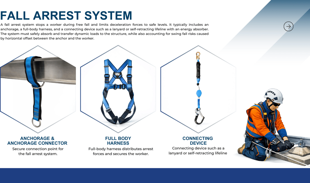
A fall arrest system is designed to stop a worker who has entered free fall and limit deceleration forces to survivable thresholds
A typical system includes:
The defining condition is the dynamic load event. The system must absorb and transfer energy safely into the structure without exceeding allowable force limits.
Swing fall must also be evaluated. Horizontal offset between anchor and user creates pendulum effects that may result in worker hitting the ground, side structures or severed suspension line due to abrasion against top edge of structure.
During a fall, gravitational potential energy converts into kinetic energy. The fall arrest system must dissipate this energy through controlled deceleration. Peak arrest force is influenced by worker mass, fall distance, and energy absorption capacity.
Increasing deceleration distance reduces peak arrest force. However, greater deceleration requires increased clearance below the user. System configuration therefore becomes a balance between force limitation and available geometry. Maximum free fall distance must be within the limits prescribed by regulations and advisory standards.
Dynamic arrest forces significantly exceed static body weight. Structural supports must resist peak load transmission rather than nominal user weight. Catenary loads significantly amplify loads imposed on anchors in a horizontal lifeline system. This distinction governs anchorage specification and load path design.
Early coordination with façade interfaces, waterproofing layers, and insulation systems ensures permanent integration without compromising envelope integrity.
Accurate clearance calculation is fundamental to safe design.
Fall Clearance = Lanyard Length + Deceleration Distance + Line Stretch + Worker Height + Safety Factor
Where:
Mounting height directly influences free fall distance. Self-retracting lifelines typically reduce free fall compared to fixed lanyards.
Performance Criteria
Specifications should define minimum anchorage capacity, maximum allowable arrest force, and required clearance geometry. Performance must be validated through structural calculation.
Environmental Classification
Exposure conditions determine material selection and coating systems to prevent long-term degradation.
Inspection and Verification Requirements
Permanent systems require documented inspection intervals and post-installation verification testing aligned with jurisdictional standards.
Rescue Integration Planning
Arrest without retrieval introduces secondary risk. Anchor positioning and access strategy must allow safe and efficient rescue procedures.
Fall arrest systems must comply with regulations in the jurisdiction of installation. Regulatory frameworks establish minimum performance thresholds, while engineering best practice frequently exceeds them.
Common global regulatory families include:
Region |
Primary Regulatory Framework |
| United States | Occupational Safety and Health Administration, American National Standards Institute |
| Canada | CSA Group |
| Europe | EN Standards |
| United Kingdom | BS Standards |
| Australia / New Zealand | AS/NZS Standards |
| Asia / Middle East | Local OHS frameworks often aligned with EN or BS |
Compliance ensures baseline safety. However, structural integration, multi-user loading verification, and façade coordination require performance-driven engineering beyond minimum code thresholds.
Permanent fall arrest systems must be integrated into the building envelope, not retrofitted as isolated attachments. Structural continuity, façade coordination, and long-term asset management planning are essential.
Effective systems:
When engineered as part of an integrated façade access strategy, fall arrest becomes a structural safety interface that protects both personnel and the asset lifecycle.
Permanent fall arrest systems require coordinated structural design, façade integration, and regulatory alignment.
Facade Access Solutions provides engineering-driven consultancy and equipment integration for permanent access and fall arrest systems across complex building typologies.
Contact our technical team to evaluate your project requirements and develop a performance-based solution aligned with structural and operational objectives.
What structural load should an anchorage be designed to resist in dynamic arrest conditions?
Anchorage design must account for peak arrest forces rather than static body weight. Dynamic loads generated during a fall can significantly exceed nominal user mass. The required capacity depends on regulatory framework and system configuration, but design should verify ultimate load resistance, load path integrity, and structural amplification effects, particularly in horizontal lifeline systems where end anchor reactions increase.
How does fall clearance differ between fixed lanyards and self-retracting lifelines?
Fixed lanyards typically permit greater free fall distance before energy absorption begins, resulting in increased clearance requirements. Self-retracting lifelines limit free fall by automatically retracting slack, thereby reducing total fall distance, but this may not be the case if swing fall is considered. However, mounting height and anchorage location remain critical variables that influence performance and required safety margins.
When should a horizontal lifeline system be specified instead of single-point anchors?
Horizontal lifelines are appropriate when continuous edge mobility is required, such as façade maintenance or roof perimeter inspections. They allow uninterrupted travel along defined paths. Single-point anchors are suitable for localized tasks. Structural analysis must confirm that end anchors can resist amplified reactions under single or multi-user loading.
How does multi-user loading affect end anchor design?
When multiple users are connected to a horizontal lifeline, combined loading and cable deflection increase end anchor reactions. The resulting structural demand may exceed individual arrest forces. Design must account for worst-case simultaneous loading scenarios and verify that supporting structural elements can safely resist amplified forces.
What inspection intervals apply to permanent fall arrest systems in global practice?
Inspection intervals vary by jurisdiction but generally include pre-use visual checks, periodic competent person inspections, and formal annual examinations. Some regions require load testing after installation or major modification. Asset owners should implement documented inspection programs aligned with applicable regulatory frameworks and manufacturer guidance to maintain compliance and system integrity.