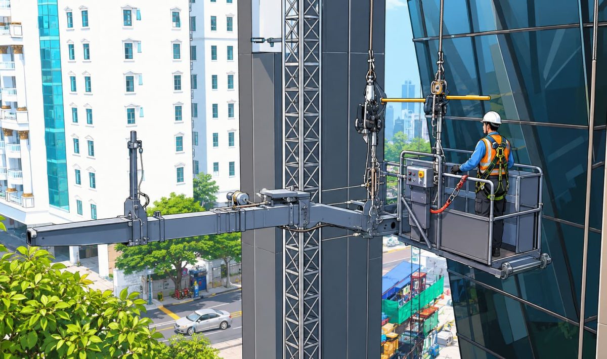
Facade maintenance teams operate on suspended platforms at height, where system performance directly determines safety. The margin between controlled operation and a serious incident depends on how well the building maintenance unit is engineered. Safety in building maintenance units is not a compliance exercise. It is an integrated engineering discipline, built into every component from hoisting systems to control interfaces. A properly specified BMU combines mechanical, electrical, and structural safeguards that function together under real operating conditions.
For architects, developers, and facility managers, understanding these safety features is critical. It defines whether a facade access system will perform reliably over decades of use while meeting regulatory, operational, and liability requirements.
Working at height remains one of the leading causes of serious injury and fatality in construction and building maintenance globally. This is reflected across major regulatory frameworks, including OSHA 1910.66 in North America, EN 1808 in Europe, and AS 1418.13 in Australia, along with aligned standards across the Middle East and Asia-Pacific. The risks for operators using building maintenance units are highly technical and often compounded by environmental and operational variables. Platform instability can arise from uneven load distribution, sudden movement, or facade geometry that introduces lateral forces. Mechanical failure during descent presents one of the most critical risk scenarios, particularly if redundancy systems are not properly engineered or maintained.
Suspension systems introduce their own set of risks. Wire ropes are subject to fatigue, corrosion, and progressive wear, especially under cyclic loading conditions. These issues can develop into structural vulnerabilities without proper monitoring and maintenance. Sudden power loss is another key risk factor, interrupting movement while the platform is suspended and requiring immediate access to controlled descent systems.
Wind loading further complicates operation. High-rise buildings experience variable wind conditions that can introduce oscillation, affect platform positioning, and increase stress on both mechanical and structural components. At the same time, poorly designed control systems can increase the likelihood of operator error, particularly in high-pressure or low-visibility conditions. These risks are well understood across the industry, which is why safety features in building maintenance units are not optional upgrades. They are fundamental system requirements that support safe operation, regulatory compliance, and long-term reliability.
Safety in building maintenance units must be addressed at the design stage. It cannot be effectively introduced after installation without significant cost, limitation, or compromise. Early-stage coordination between facade access specialists, architects, and structural engineers defines how the system will perform under real operating conditions. Roof structures must be engineered to support both static loads and dynamic forces generated by BMU movement, including lifting, traversing, and wind-induced stresses.
At this stage, several critical design factors are defined:
From a developer and building owner perspective, these design decisions carry direct long-term implications:
These risks do not remain isolated. They compound over time as the system is used, inspected, and maintained. Engaging an experienced facade access specialist at concept stage ensures that these variables are addressed early. This approach aligns structural design, access strategy, and safety systems from the outset, reducing long-term liability while supporting consistent, compliant operation throughout the building lifecycle.
Mechanical systems form the foundation of building maintenance unit safety. They are responsible for lifting, load control, movement stability, and redundancy under both normal and fault conditions.
Modern BMUs rely on multi-layer safety drum hoists as the standard for suspension. Unlike traction-based systems, drum hoists wind the suspension rope onto a drum, reducing slip risk and improving control over load movement. This configuration also minimizes rope wear, particularly in high-cycle applications. Braking systems are engineered with multiple layers of redundancy. The primary braking mechanism is typically an electromagnetic motor brake, which controls movement during normal operation. This is complemented by a secondary safety brake that acts directly on the winch drum. If the system detects excessive speed or uncontrolled descent, this brake engages automatically.
A third layer of protection is often provided by centrifugal braking mechanisms. These systems activate when rotational speed exceeds predefined thresholds, ensuring that even in extreme fault conditions, movement is brought under control. Manual descent devices are an essential component of this system. In the event of power loss, operators must be able to lower the platform safely using a controlled mechanical mechanism. This is a baseline requirement under EN 1808 and equivalent standards.
Suspension systems are designed around redundancy and durability. A compliant BMU uses four independent wire ropes, each capable of supporting the platform load. This ensures that failure in one rope does not result in platform collapse. These ropes are typically manufactured from galvanised high-tensile steel and individually certified. Diameter ranges between 7 mm and 14 mm depending on system configuration and load requirements. EN 1808 specifies a minimum safety factor greater than 12, meaning each rope must withstand loads significantly higher than its operational requirement.
Rope guidance systems are critical for maintaining performance. Large-diameter pulleys reduce bending stress and friction, extending rope life. Materials such as PA6 are commonly used for their strength and wear resistance. Slack rope detection systems provide continuous monitoring of rope tension. If a rope loses tension unexpectedly, the system identifies the condition and triggers alerts or shutdown procedures before it develops into a structural issue.
Overload protection systems monitor platform weight in real time. If the load approaches the rated working limit, the system prevents further movement, ensuring that structural and mechanical limits are not exceeded. Typical BMU systems operate within a capacity range of 240 kg to 1,000 kg. Overload protection ensures that operation remains within this range under all conditions. Additional sensors at suspension attachment points provide localized monitoring at critical load transfer interfaces.
BMUs operating on roof-mounted tracks must maintain stability during horizontal movement. Anti-derailment systems use mechanical gripping devices and clamps to secure the unit to the rail, particularly under wind loading or uneven movement conditions. Traversing systems are designed with soft-start and soft-stop functionality to eliminate sudden acceleration or deceleration. This reduces structural stress and improves operator control. Integrated braking systems ensure that the unit remains fixed in position when not in motion, preventing drift along the track.
Electrical systems provide real-time monitoring and control, ensuring that the BMU responds immediately to changing conditions and potential faults.
Emergency stop systems are positioned at all control points, including the cradle and roof car. These controls allow operators to immediately halt all movement in the event of an issue. Each emergency stop function operates independently, ensuring that failure in one circuit does not compromise the system’s ability to shut down safely. This redundancy is critical in maintaining control during fault conditions. Dead-man controls further enhance safety by requiring continuous operator input for movement. Releasing the control stops the platform instantly, reducing the risk of unintended operation.
Modern BMUs incorporate a range of sensors to monitor operational conditions. Obstruction sensors detect objects in the path of movement and trigger automatic shutdown to prevent collision. Wind speed sensors continuously measure environmental conditions and halt operation when limits are exceeded. End-position sensors define the upper and lower travel limits of the platform, preventing over-travel. Tilt and anti-tilt sensors monitor platform alignment, ensuring that load distribution remains stable. In advanced systems, automatic levelling functions actively correct imbalance during operation.
Control interfaces are designed to minimize operator error. Human Machine Interfaces provide clear visual feedback through LCD displays, showing system status, fault conditions, and operational parameters. Each function is controlled through a dedicated switch, reducing ambiguity and preventing accidental activation. Control systems typically operate on low-voltage architecture, improving safety and reducing electrical exposure.
Electrical interlocks prevent operation under unsafe conditions. Key-operated systems restrict access to authorized personnel and ensure that the BMU cannot be started unless all safety parameters are met. Motor synchronization systems monitor multiple drive units to ensure even load distribution. If imbalance is detected, the system shuts down automatically to prevent structural stress or mechanical failure. Remote diagnostics through PLC systems allow technicians to monitor performance, identify faults, and plan maintenance without requiring immediate on-site intervention.
A building maintenance unit must ensure safe recovery under all conditions. Emergency retrieval systems are a core design requirement, not an optional feature.
Manual descent devices allow operators to lower the platform safely during complete power failure. These systems provide controlled movement independent of electrical power and are required under all major standards. Some systems include backup power to support limited controlled descent before manual operation is required. This adds an additional layer of operational resilience.
Redundancy in braking systems ensures that no single failure can result in uncontrolled movement. Multiple independent braking mechanisms operate automatically, providing consistent response regardless of the failure scenario. These systems are designed to engage without operator input, ensuring immediate action even in high-stress conditions.
Emergency retrieval is integrated into system geometry. The BMU must be able to position the cradle in a location where operators can be safely recovered. At the same time, maintenance personnel must be able to access the unit without exposure to additional risk. This requires coordinated design of jib reach, articulation range, and slewing capability. These factors are evaluated during system specification to ensure practical and safe recovery procedures.
Safety performance is sustained through proper testing, maintenance, and operation.
All BMUs undergo full functional testing before delivery. This includes validation against relevant standards and regulations such as EN 1808, OSHA 1910.66, ASME A120.1, CSA Z91, CSA Z271, AS 1418.13, and ISO 9001. Key components, including structural assemblies, suspension systems, and electrical controls, are tested to confirm performance under operational conditions. Documentation from this process forms part of the system’s compliance record.
A structured maintenance program is essential. Pre-use inspections identify visible issues before operation. Quarterly rope inspections assess wear, diameter, and structural integrity. Annual audits provide independent verification of system condition. All inspections must be documented. Maintenance records support regulatory compliance, insurance requirements, and long-term system evaluation.
While BMU operation does not require rope access certification, it does require structured training. Operators must understand system controls, safety features, inspection procedures, and emergency protocols. Training ensures consistent operation and reduces the likelihood of user-related incidents.
BMU systems are designed as integrated units. Using non-OEM components can compromise safety and invalidate certifications. Replacement parts must meet original specifications and be installed by qualified technicians to maintain system integrity.
Selecting a building maintenance unit requires a detailed assessment of how the system performs under real operating conditions.
Start with early design integration. Safety is most effective when it is engineered into the system from the beginning, not added later. Request full technical transparency. A reliable provider should clearly define every safety feature, including braking systems, sensor coverage, and emergency protocols. Evaluate long-term value rather than upfront cost. Systems that require modification or fail inspection introduce greater risk and expense over time. Prioritize lifecycle support. Ongoing maintenance, training, and access to genuine components are essential to maintaining safe and reliable operation.
Facade Access Solutions works with architects, developers, and facility managers across global markets to specify, supply, and support building maintenance units designed for long-term safety and performance.
Disclaimer: Graphics shown are illustrative only and do not represent actual products, equipment, or real-life conditions.
Speak with our specialists to explore the right solution for your building.
ContactMulti-layer braking systems, four independent suspension ropes, overload protection, and sensor-based monitoring are the most critical. These systems provide redundancy and ensure controlled response under fault conditions.
Pre-use checks should be carried out before every operation. Detailed inspections are typically conducted every three months, with annual third-party audits required to maintain compliance.
EN 1808 applies in Europe and the UK. OSHA 1910.66 and ASME A120.1 apply in North America. AS 1418.13 applies in Australia, with other regions aligning to these frameworks.
A properly designed system includes a manual descent device that allows controlled lowering of the platform. Some systems also include backup power for limited operation before switching to manual control.
Some upgrades are possible, such as sensors and control systems. However, full compliance may require system replacement depending on the original design limitations.