BMU design is not a downstream decision. It is a core part of how a building is engineered, accessed, and maintained over its entire lifecycle.
When building maintenance unit design is addressed late, the consequences are immediate and costly. Structural retrofits become unavoidable. Facade access is compromised. Compliance risks increase. What should have been an integrated system becomes a constraint.
For architects, engineers, and developers, BMU design extends far beyond equipment selection. It defines how mechanical systems interact with the building structure and how access is achieved across every section of the facade. Jib configuration, hoist selection, traversing systems, and platform design must align with roof load capacity, parapet conditions, and architectural intent from the outset.
Building height, facade geometry, and roof configuration directly determine the BMU strategy. At the same time, compliance with standards such as EN 1808, OSHA 1910.66, ASME A120.1, and AS/NZS 1418.13:2013 must be embedded into the design. These are not final-stage checks. They are engineering constraints that shape the system from day one.
Effective BMU design sits at the intersection of structural engineering, mechanical systems, and architecture. These disciplines must be resolved together to ensure safe operation and full facade coverage.
A well-engineered BMU begins with a clear understanding of the building.
Building height determines hoist configuration and rope length. For structures above 125 metres, multi-layer drum hoists are typically required. Modular and custom BMUs with multi-layer drum hoists service buildings well beyond 300 m. Multi-stage configurations have been deployed on the Burj Khalifa (828 m), Merdeka 118 (679 m), and Shanghai Tower (632 m).
Facade complexity dictates jib configuration. Uniform facades may require only a fixed arm, while recessed, stepped, or curved geometries demand telescopic, luffing, or articulated designs.
Roof structure defines the system type. Load-bearing roofs support track systems, while non-load-bearing roofs require parapet-mounted solutions. Concrete runway systems provide an alternative where track installation is not viable.
Available roof space affects parking and concealment strategy. Whether the BMU is stored openly, within a garage, or in a recessed pit must be considered early.
Facade coverage requirements determine whether a single BMU is sufficient or if additional systems are needed.
EN 1808:2015 §6.1.2.5 specifies a minimum static safety factor of 12 on each suspension rope (i.e. rope MBL ≥ 12 × maximum static rope tension). This drives rope diameter selection — typically 7–14 mm depending on cradle length, payload, and reeving. In North America OSHA and CSA require suspension wire ropes to respect a safety factor of 10:1.
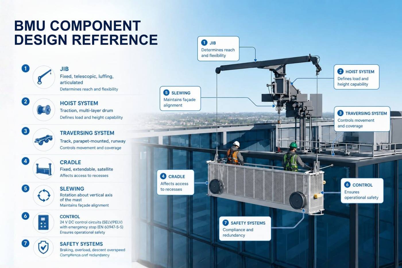
A BMU is a fully configured system. Each component defines façade coverage, safety, and integration with the building.
| Component | Key Options | Design Impact | When to Use |
|---|---|---|---|
| Jib | Fixed, telescopic, luffing, articulated | Determines reach and flexibility | Telescopic/articulated for complex facades |
| Hoist System | Traction, multi-layer drum | Defines load and height capability | Drum hoists for tall buildings |
| Traversing System | Track, parapet-mounted, runway | Controls movement and coverage | Parapet/runway for constrained roofs |
| Cradle | Fixed, extendable, satellite | Affects access to recesses | Extendable/satellite for complex facades |
| Slewing | Rotation about vertical axis of the mast | Maintains facade alignment | Required for corners and curves |
| Control | Control circuits operate at extra-low voltage (typically 24 V DC) in line with EN 1808’s SELV/PELV requirement. Emergency-stop functions with positive-opening contacts (EN 60947-5-5) are mandatory. | Ensures operational safety | Standard across all systems |
| Safety Systems | Braking, overload, descent overspeed | Compliance and redundancy | Mandatory under EN/OSHA |
The jib determines how the BMU interacts with the facade and whether full access can be achieved.
| Facade Condition | Recommended Jib Type | Reason |
|---|---|---|
| Moderate recesses | Telescopic jib | Adjustable outreach |
| Sloped roofs | Luffing jib | Vertical clearance capability |
| Complex geometry | Articulated jib | Multi-point flexibility |
| Highly complex structures | Telescopic + rotating hoist | Maximum access capability |
Fixed jibs suit simple facades, while telescopic and articulated designs allow the system to adapt to complex geometries. Luffing jibs introduce vertical movement, enabling the arm to clear architectural elements. A slewing head ensures the cradle remains parallel to the facade during operation.
The hoist defines vertical movement and operational limits. Personnel cradle SWL is capped at 1,000 kg under EN 1808. Standard configurations support 240–500 kg; modular cradles reach 1,000 kg. Material-only hoists (governed by EN 14492-1 rather than EN 1808) extend beyond personnel limits when separate equipment-lifting use cases are designed in.
Typical operational lifting speeds are 9–11 m/min, well within the 18 m/min ceiling EN 1808 §5.3.7 sets for permanently installed cradles. Traversing speeds typically range 10–15 m/min.
Traversing systems determine how the BMU moves across the building.
Horizontal tracks are the most common where roof space allows. Parapet-mounted systems transfer loads to the building edge and suit non-load-bearing roofs. Concrete runway systems operate without tracks, using wheeled movement across a load-bearing surface.
Shunting systems allow the BMU to move into garages or concealed positions. For sloped or curved roofs, inclined or rack-and-pinion systems with self-levelling ensure stability.
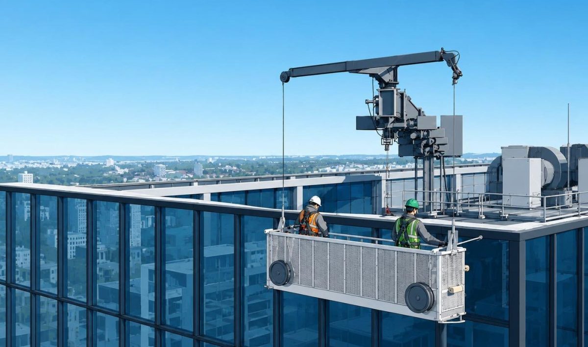
The cradle is the working platform, typically constructed from aluminium with integrated safety systems.
Cradles are typically suspended on a working rope plus an independent secondary safety rope at each suspension point — so a twin-suspension cradle commonly runs four lines (two working + two safety). The exact configuration depends on cradle length, SWL, and EN 1808 redundancy provisions.
Extendable platforms and satellite cradles improve access across complex facades. Slewing functionality ensures alignment with the facade, while safety features such as braking and controlled descent are mandatory under EN 1808 and ASME standards.
Selecting the right BMU design prevents both over-engineering and under-specification.
| Design Factor | Compact BMU | Crane-Type BMU | Modular / Custom BMU |
|---|---|---|---|
| Building Height | Up to 270 m | Up to 270 m | 270 m+ |
| Facade Complexity | Simple | Moderate | Complex |
| Jib Type | Fixed/basic | Slewing | Telescopic/articulated |
| Reach | Limited | Moderate | High |
| Roof Constraints | Low | Moderate | Flexible |
| Load Capacity | 240–500 kg | 240–500 kg | Up to 4,200 kg |
| Best Use | Standard buildings | Buildings with obstructions | Iconic or high-rise buildings |
Modern BMU design incorporates concealment strategies to minimise visual impact.
| Method | How It Works | Design Requirement | Best For |
|---|---|---|---|
| Parking Pit | Retracts below roof | Structural integration | Zero visibility |
| Garage | Enclosed storage | Space and clearance | Concealed systems |
| Integrated | Built into structure | Early collaboration | Design-led buildings |
| Track Concealment | Hidden behind parapet | Precise positioning | Low visibility |
| Curved Traversing | Moves along facade | Custom track design | Curved buildings |
Parking pits and garages provide full concealment, while integrated solutions embed the BMU into the building structure. These approaches require early coordination between design disciplines.
Curved and irregular facades require specialized engineering. Track systems must follow building geometry, supported by self-levelling and pivoting mechanisms.
Advanced systems allow multi-directional movement, ensuring safe operation across complex surfaces.
Visibility is controlled through system height, positioning, and colour matching. Compact BMUs are designed to sit below parapet level, minimizing visual impact.
Late-stage BMU decisions lead to avoidable constraints. Early IDS integration ensures proper system coordination, compliance, and full facade coverage.
Facade Access Solutions delivers integrated design support (IDS) from early-stage planning through installation and lifecycle service. With over 16,000 systems installed globally and engineering teams across key regions, the company delivers proven expertise across complex projects.
Engage IDS planning early to ensure efficient integration, compliance, and long-term facade access performance.
Speak with our specialists to explore the right solution for your building.
Request a Quote TodayCompact BMUs are designed for simple facades with consistent access requirements. Modular BMUs provide greater flexibility and are suited to complex or high-rise buildings.
BMU design should begin during early architectural and structural planning to ensure proper integration and avoid retrofits.
Custom track systems and articulated movement allow BMUs to follow building geometry while maintaining stability.
BMU systems must comply with EN 1808, OSHA 1910.66, ASME A120.1, and AS/NZS 1418.13:2013.
Yes, but structural assessment is required to determine feasibility and system configuration.